overview components memorymap downloads possibilities contact
 
processor memory via acia
The Amélie project
Components
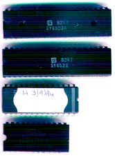
Amélie consists of a number of hardware components, the basic parts can be seen in the picture on the right.

Part of Amélie's design philosophy is "keep it simple", so only the minimum required is used. There is nothing "fancy", as a system capable of rendering 3D images in real-time may look good on paper, but it won't run your heating any better, nor will it make a better burglar alarm.

What works is to keep it simple, keep it effective, and do exactly what is required with the minimum of fuss and bother.
Amélie's component parts.

The component parts of Amélie are:

    • The processor
      A 6502, expected to be clocked at 2MHz; though I'll have to confirm that my VIA is a 2MHz part as this will affect the overall decision.

    • The "memory"
      2K of static RAM, 8K of EPROM, and memory-mapped I/O devices.

    • The digital I/O
      A 6522 VIA, offering 16 digital I/O lines and two timers.

    • The serial I/O
      A 6551 ACIA, running at 9600bps 8N1, for communication with the "outside world". The evidently-slow serial port speed is to allow communication with pretty much anything, as well as not swamping AmélieEm with serial port interrupts. It will suffice, we aren't going to try downloading megabytes of stuff, remember!

      The 6551 requires a 1.8432MHz crystal to correctly generate the baud rates, and it may be that this is used as the master clock source (via the CPU, Ř2?). So long as the VIA Timer1 period is adjusted to maintain a constant 50Hz 'ticker', then the actual system clock speed is not really that relevant. In this case, 1843200÷50 is 36864, so this value should be loaded into Timer1 instead of the 40000 that 2MHz would require.


Two components that do not have their own documents are:

    • The latch. Mapped in at &A300 , this device appears as a single byte in the memory map. The value written to this byte is held until the next time it is updated (or 'latched', hence the name). The lower four bits represent LEDs - bit 3 is red, bits 2 and 1 are yellow, bit 0 is a green LED. The upper four bits are unused.
       
    • Small diagram of options extension.The options selector. Optionally mapped in at &A200, this device is basically a buffer wired up in 'reverse', which will make the values of up to seven selection switches available to the processor when addressed. This is not part of the original Amélie specification, though I mention it here as it may be incorporated on the final board. It only requires three components - a small IC (a 74LS244), a resistor pack, and a bank of microswitches.
      The purpose of this is to provide a set of "options" to alter various aspects of the behaviour of the application code, without the need to "hardwire" the desired options into EPROM and burn off multiple versions. In the long run, the options selector is much more efficient!


You will also find the memory map useful to look at, along with the schematic (which may be found in the downloads section).

© 2007 Rick Murray