It is the 1519th of March 2020 (aka the 27th of April 2024)
You are 18.216.190.167,
pleased to meet you!
mailto:blog-at-heyrick-dot-eu
Clocks
I keep looking at the clock and thinking "that can't be right", but alas it is. It's one of the two days in the year when we mess around with the clocks.
I bought a new phone!
Not so long ago, I bought a Xiaomi Mi 10T as part of my "renew my mobile contract for another two years". I kept meaning to review the phone, but I mostly used it for making videos and watching Netflix. It has the old Bouygues SIM in it, and I think I've made maybe four calls on it (mostly to use up the €5 credit that I stick on once a year to keep the line active).
Well, would you believe it? It's been two years already.
So I get the opportunity to get myself a new phone. Even though I'm still taking my ancient Samsung S9 to work as my primary mobile, and using the Mi 10T as for video (in and out).
I mean, I might as well. It isn't as if declining the offer will cause my tariff to go down at all.
The phone I have chosen is a Xiaomi Redmi Note 12 Pro. This was chosen based upon two factors. The first, it was cheap. About €50. The second? An OLED screen, so ought to look better with Netflix. Oh, and it has an audio jack so I can use plug in headphones again.
It's about a year old (released in November 2022), and it runs Android 12 and MIUI 13 on a Mediatek MT6877V. The screen is 1080×2400 (20:9) measuring 6.67". It's the same size as the Mi 10T. It claims to support a billion colours.
The camera/hardware isn't as good as the one on the 10T: it only goes up to 50 mpix, and the video only does 4K at 30fps (as opposed to the 10T's 64Mpix and 8K/30fps). That being said, I don't tend to use the max resolutions as they take a ton of memory. I did upload a short 8K video to YouTube, which was a bit pointless as YouTube doesn't support 8K. The camera pixels are 1.0µm so it'll remain to be seen if this is better in the dark.
There's also the wide angle and a macro (but only 2Mpix).
In terms of "other stuff", it has GPS (various types), fingerprint sensor, gyro, blah blah.
However, like the 10T, it cuts corners to keep the price down. The 10T made the tradeoff of a decent processor (the same as in the Galaxy S20, actually) but a basic LCD which isn't actually that bad but in common with LCDs it can't deal with black blacks and white whites at the same time.
Other things, both only support USB 2.0 (using USB-C), and neither supports wireless charging. The battery on both is 5000mAh, though this phone comes with a 67W (!) charger and claims to half-charge it in 15 minutes (good grief!).
In terms of performance, it's not as nippy as the 10T (AnTutu ~600,000) measuring around 500,000. That being said, my primary use case for this device is to watch videos and Netflix. That ought to free up space on the 10T for more videos before I have to start dumping stuff to USB keys.
It is supposed to be delivered by Chronopost. I can but close my eyes and shake my head slowly.
Let's see, I'll call it now:
Either: We passed by, you weren't there, we dumped it someplace convenient to us for collection (having actually NOT passed by at all).
Or: We can't leave it at a collection point, and while we deliver all of the days, we won't be coming to you on a Saturday because <excuse>, so...
Netflix prices
Speaking of Netflix, they're putting their prices up again. It was, if I remember correctly, €6,99 a month when I started back in 2020. In September 2021 it went up to €8,99 "to bring you more great entertainment".
Now it will be €10,99 a month "to deliver even more value for your membership".
Well, I'm not that interested in the games as the downloads are huge, and y'all have a nasty habit of cancelling the stuff that I enjoy.
Speaking of Netflix, I've noticed a huge bump in the number of new things from Korea (and some from Japan). It's almost as if there was something stopping America from creating new programmes... ☺
DSO Shell serial interface
If you have one of these dinky little oscilloscopes, firmware versions with -110 or higher at the end support outputting the capture buffer to the serial port if you hold down V/DIV and ADJ at the same time.
Some people have written code to pull data from the serial port and reformat it for gnuplot, but being in Python and various dependencies, it's not so useful for RISC OS.
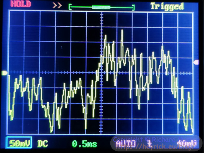
Now when it comes to blog articles, sometimes it is useful to illustrate something with a screenshot of the oscilloscope's display. And while something like this is functional, it could be... less naff.
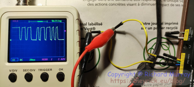
A photo of the oscilloscope's display.
You may or may not be looking at a tiny snippet of "Eventide" by Empress. ☺
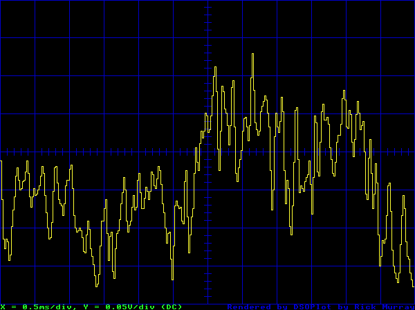
How about this for clarity?
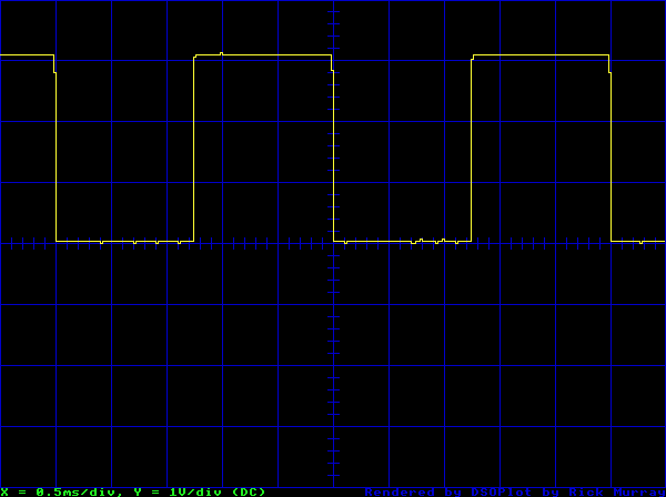
A render of the oscilloscope data.
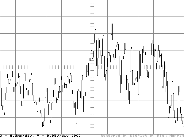
Or, considering the use case of blogs, perhaps this?
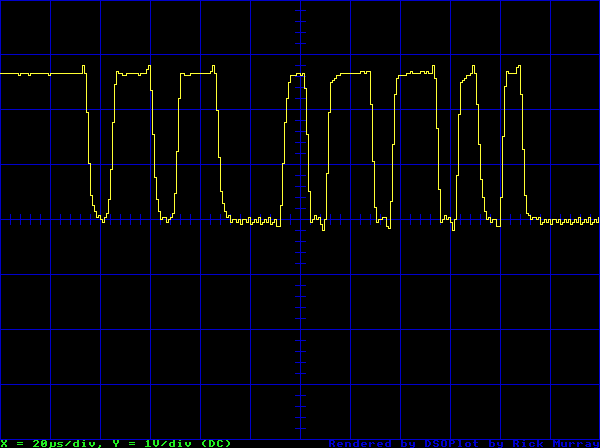
A different render of the oscilloscope data.
How it works
Using a standard data format of 115,200bps 8N1, it sends a header that looks like this:
While there are 1024 samples, we only render 300 of them, literally that which is on the screen, the offset of which is determined by the HPos value.
The data provided in the samples is, literally, the measured voltage (according to the current settings). It can be positive or negative. The middle line of the screen is 0V. However the vertical position can be adjusted. This doesn't alter the data, it changes the VPos value which needs to be merged into the recorded voltage in order to know where to actually plot the points.
We don't really need to pay that much attention to the horizontal position as we're 600 pixels wide and we'll be reading 300 points, so we just need to read and plot.
The vertical position, on the other hand, is quite a bit more complicated. We need to work out how much each square represents (in terms of volts), and then we need to use that to work out how many squares each value would require in order to get us a position relative to the centre line.
The code - setting up
Just so you know - this code has been VERY LIGHTLY TESTED and probably has bugs.
It works on the settings that I tried it with,
REM >DSOPlot
REM
REM Version 1, by Rick Murray
REM Sunday, 29th October 2023
REM https://heyrick.eu/blog/index.php?diary=20231029
REM
REM (C) 2023 Richard Murray
REM Released under the terms of the CDDL.

ON ERROR PROCerror

DIM spr% 310 * 1024 : REM 640×480 = 307200, plus some extra for headers
spr%!0 = 310 * 1024
spr%!8 = 16
SYS "OS_SpriteOp", 256+9, spr% : REM Init area

DIM buffer% 1024 : REM RX buffer
DIM d$(1043)     : REM Lines of input

width% = 600 : REM Not 640 because ÷ 12 *AND* the 'scope draws 300 points across the screen
height% = 440
bottom% = 40
hstep% = height% / 8
vstep% = width% / 12
darkmode% = TRUE
Nothing unusual there. We've set the display to be 600 by 440, with 40 pixels at the bottom for messages. This has been broken into 8 squares up and down, and 12 across, just like the oscilloscope.
Getting going
REM Open serial device - assumes there's one serial USB device and we're it.
device$ = "SerialUSB#noblock;sleep;nohandshake;baud=115200;data=8;stop=1;noparity:"
in% = OPENIN(device$)

gotsomedata% = FALSE : REM Disallow keypresses until valid data

MODE 28
OFF
COLOUR 0, 255, 255
PRINT "Press V/DIV and ADJ on your DSO Shell to send data..."
Opens the serial device (you'll need Colin's SerialUSB module, obviously) and plops some text on the screen so you know that the program is awaiting input.
Reading from the serial port
thisptr% = -1
REPEAT
  SYS "OS_GBPB", 4, in%, buffer%, 1024 TO ,,end%,not%
  bufptr% = buffer%
  WHILE end% > bufptr%
    byte% = ?bufptr%
    bufptr% += 1
    IF (thisptr% = -1) THEN
      IF (byte% = 13) THEN d$(0) = ""
      IF (byte% > 31) THEN
        d$(0) += CHR$(byte%)
        REM The very first byte should be a 'V', so if we see it, begin from there
        IF (byte% = ASC("V")) THEN d$(0) = "V"
      ENDIF

      REM If we see "VSen", this is the first line
      IF d$(0) = "VSen" THEN
        thisptr% = 0
        PRINT "Synced, receiving..."
        FOR loop% = 1 TO 1042
          d$(loop%) = ""
        NEXT
      ENDIF
    ELSE
      IF (byte% = 13) THEN thisptr% += 1
      IF (byte% > 31) THEN
        d$(thisptr%) += CHR$(byte%)
      ENDIF

      REM In case resync needed
      IF d$(thisptr%) = "VSen" THEN
        d$(0) = d$(thisptr%)
        thisptr% = 0
        PRINT "Resynced, receiving..."
      ENDIF
    ENDIF
  ENDWHILE
A lot of this code is concerned with trying to sync ourselves, as we don't know the state of the serial port when we begin, and the oscilloscope outputs this as it boots:
So we keep reading data into the first string until we find a 'V', and if we find that we'll clear the buffer to be only 'V'. Then we look for "VSen", and if we find that we know we're synced.
We also check if the input to another line matches in case there's some data missing to try to resync. Though in my testing (on a Pi 2), this wasn't necessary.
However, sometimes it doesn't correctly sync at the start so you might need to send the data twice the first time.
Anyway, this just keeps reading whatever comes in to the string array, and incrementing the array pointer every time a carriage return is received. We ignore linefedds (the termination in use is CRLF).
When we have data
  REM Have we read it all?
  IF (thisptr% = 1043) THEN
    gotsomedata% = TRUE

    PROCreadsettings

    PROCdrawscreen

    PROCplotpoint(0, VAL(MID$(d$(hstart% + 19), 18)), FALSE)
    FOR plotloop% = hstart% TO hstart% + 299
      val = VAL(MID$(d$(plotloop% + 19), 18))
      PROCplotpoint(plotloop% - hstart%, val, TRUE)
    NEXT

    thisptr% = -1
  ENDIF
When we have read 1043 lines of data, that's 19 header lines and 1024 lines of samples, then it's time to do something about it.
We'll flag that we have data, and then pull out the settings for the scope so we know what needs done.
Next, we'll draw the screen.
After that, we read and calculate the leftmost point, but it's not drawn on the screen. It is simply remembered, so we know where the trace will begin.
Then we read all 300 points and plot them.
Finally, the string array pointer is set back to -1 so we know we'll be starting again the next time data comes in.
Keypresses and loop end
  IF gotsomedata% THEN
    k% = INKEY(1)
    IF (k% = 83) OR (k% = 115) THEN
      buffer%?64 = 3
      SYS "OS_Word", 14, buffer%+64
      SYS "Territory_ConvertTimeToOrdinals", -1, buffer%+64, buffer%
      ye% = buffer%!&18
      mo% = buffer%!&14
      da% = buffer%!&10
      ho% = buffer%!&0C
      mi% = buffer%!&08
      se% = buffer%!&04
      sn$ = RIGHT$("0000"+STR$(ye%),4)+RIGHT$("00"+STR$(mo%),2)
      sn$+= RIGHT$("00"+STR$(da%),2)+RIGHT$("00"+STR$(ho%),2)
      sn$+= RIGHT$("00"+STR$(mi%),2)
      fi$ = sn$ + RIGHT$("00"+STR$(se%),2)
      l%  = 0
      b%  = (bottom% - 8) << 1
      r%  = (width% - 1) << 1
      t%  = (height% + bottom% - 1) << 1
      SYS "OS_SpriteOp", 256+16, spr%, sn$, 0, l%, b%, r%, t%
      SYS "OS_SpriteOp", 256+12, spr%, fi$ : REM Save it (to the current directory)
      SYS "OS_SpriteOp", 256+25, spr%, sn$ : REM Delete it (for next time)
    ENDIF

    REM 'D' or 'd' to toggle darkmode
    IF (k% = 68) OR (k% = 100) THEN
      darkmode% = darkmode% EOR TRUE
      PROCdrawscreen
      PROCplotpoint(0, VAL(MID$(d$(hstart% + 19), 18)), FALSE)
      FOR plotloop% = hstart% TO hstart% + 299
        val = VAL(MID$(d$(plotloop% + 19), 18))
        PROCplotpoint(plotloop% - hstart%, val, TRUE)
      NEXT
    ENDIF
  ENDIF
UNTIL FALSE

END

:
This is primarily two blocks. The top block deals with saving a screenshot as a sprite. It reads the active area of the screen, plus the status line just below, as a sprite. The faffing around with buffer% and Territory is in order to name the sprite according to the time ("YYYYMMDDhhmm") and setting the filename as "YYYYMMDDhhmmss". We don't have seconds in the sprite name as there are only twelve characters available.
The bottom block toggles the dark mode setting and then does a redraw of the screen and the points.
The loop repeats forever. Press Escape to finish.
Reading the settings
DEFPROCreadsettings
  REM Get what the vertical divisions are
  vsens = VAL(MID$(d$(0), 6))
  IF (RIGHT$(d$(0), 2) = "mV") THEN
    REM Translate mV to V/div
    IF vsens = 50 THEN vdiv = 0.05
    IF vsens = 20 THEN vdiv = 0.02
    IF vsens = 10 THEN vdiv = 0.01
    IF vsens = 5  THEN vdiv = 0.005
  ELSE
    REM We can use the larger values as-is
    vdiv = vsens
  ENDIF

  REM Get the coupling
  IF (RIGHT$(d$(1), 2) = "AC") THEN
    accouple% = TRUE
  ELSE
    accouple% = FALSE
  ENDIF

  REM Get how much we have to fudge things for the correct vertical position
  vfudge = VAL(MID$(d$(2), 6))
  IF (RIGHT$(d$(2), 2) = "mV") THEN vfudge = vfudge / 1000

  REM Now get the horizontal divisions
  hsens = VAL(MID$(d$(3), 10))
  REM Now convert to microseconds
  IF RIGHT$(d$(3), 2) = "us" THEN
    REM Microseconds, do nothing
    hdiv = hsens
    hsuffix$ = "µs"
  ELSE
    IF RIGHT$(d$(3), 2) = "ms" THEN
      REM Milliseconds, convert to microseconds
      hdiv = hsens * 1000
      hsuffix$ = "ms"
    ELSE
      REM Must be seconds, convert to microseconds
      hdiv = hsens * 1000000
      hsuffix$ = "s"
    ENDIF
  ENDIF

  REM Get the screen start position
  hstart% = VAL(MID$(d$(4), 6))
ENDPROC
This parses out the data we're interested in from the header so we'll know how to scale stuff.
Drawing the screen
DEFPROCdrawscreen
  LOCAL loop%, innerloop%, dashstep

  IF NOT darkmode% THEN
    COLOUR OF 0,0,0 ON 255,255,255 : REM Set text to be black on white
  ELSE
    COLOUR OF 255,255,255 ON 0,0,0 : REM Set text to be white on black
  ENDIF
  CLS

  REM Outer border
  IF darkmode% THEN
    GCOL 0,0,255         : REM Blue
  ELSE
    GCOL 132, 132, 132   : REM Mid grey
  ENDIF
  RECTANGLE 0, bottom% << 1, (width% - 1)<<1, (height% - 1)<<1
Okay, this first part sets the foreground and background colours and then clears the screen. This is followed by drawing a rectangle around the work area.
  REM Horizontals
  FOR loop% = 0 TO (height% - 1) STEP hstep%
    MOVE 0, (loop% + bottom%) << 1
    DRAW (width% - 1) << 1, (loop% + bottom%) << 1
  NEXT

  REM Verticals
  FOR loop% = 0 TO (width% - 1) STEP vstep%
    MOVE loop% << 1, bottom% << 1
    DRAW loop% << 1, (height% + bottom%) << 1
  NEXT
This draws the grid.
  REM Now dash the middle horizontal line
  dashstep% = vstep% / 5
  FOR loop% = 0 TO (width% - 1) STEP dashstep%
   MOVE loop% << 1, ((bottom% + (4 * hstep%)) - 5) << 1
   DRAW loop% << 1, ((bottom% + (4 * hstep%)) - 5) << 1
  NEXT

  REM Now dash the middle vertical line
  dashstep% = hstep% / 5
  FOR loop% = 0 TO (height% - 1) STEP dashstep%
   MOVE width% - 10, (bottom% + loop%) << 1
   DRAW width% + 10, (bottom% + loop%) << 1
  NEXT
This adds in the dashed line on the middle axes.
  VDU 31, 0, 55
  IF darkmode% THEN
    COLOUR 0, 255, 0     : REM Green
  ELSE
    COLOUR 0, 0, 0       : REM Black
  ENDIF
  oldat% = @%
  @% = "+G.3"
  PRINT "X = "+STR$(hsens)+hsuffix$+"/div, ";
  PRINT "Y = "+STR$(vdiv)+"V/div (";
  IF (accouple% = TRUE) THEN PRINT "AC"; ELSE PRINT "DC";
  PRINT ")"
  IF darkmode% THEN
    COLOUR 0, 0, 255     : REM Blue
  ELSE
    COLOUR 192, 192, 192 : REM Light grey
  ENDIF
  VDU 31, 41, 55
  PRINT "Rendered by DSOPlot by Rick Murray"
  IF darkmode% THEN
    COLOUR 0, 255, 255   : REM Cyan
  ELSE
    COLOUR 0, 0, 0       : REM Black
  ENDIF
  PRINT "Press [S] to save this as a sprite, or [D] to toggle dark mode"
  PRINT "Send more data to update display, or [Esc] to quit."
  VDU 31, 0, 0
  @% = oldat%
ENDPROC
This displays the text at the bottom of the screen.
Of note is the line setting @% to "+G.3". This means general floating point with up to three decimal places, and also apply this formatting to STR$.
This provides sensible results for all but the 5mV/div setting which appears as 5E-3. Changing @% to "+G.5", for example, doesn't work. What will work is to use the option "+F.4", but the side effect of that is that every number will have four decimal places.
I could probably add some more code to fix this quirk in how BASIC displays floating point values, but to be honest for the most sensitive range that'll likely be a mass of interference from the environment, it's not really worth it.
Plotting points
DEFPROCplotpoint(xpos%, value, doplot%)
  REM Apply fudge
  value += vfudge

  REM Now we have a volts reading, so how many divisions to plot this?
  divs = value / vdiv

  REM Now what's the offset from the middle? (middle point is 0V)
  ypos = (bottom% + (4 * hstep%)) + (divs * vstep%)
  REM    |---- middle point ----|   |--- divs ---|

  IF ( doplot% = FALSE ) THEN
    MOVE xpos% << 2, ypos << 1
  ELSE
    IF darkmode% THEN
      GCOL 255, 255, 0 : REM Yellow
    ELSE
      GCOL 0, 0, 0     : REM Black
    ENDIF
    DRAW xpos% << 2, prevypos << 1
    DRAW xpos% << 2, ypos << 1
  ENDIF

  prevypos = ypos
ENDPROC
What we're doing here is adjusting the input voltage according to the vpos setting. Then we're dividing it by how much each division represents. So if, for example, we're in 1V/div mode and the input is 2.5, then the result will be 2.5 divisions.
This is then calculated as an offset from the middle (0V) line.
The only other thing that might need explanation is the two DRAW statements. What's going on here is that the previous sample is being prolonged to the new position, and then we're jumping to the new position.
Why this is being done is in order to keep the vertical lines of voltage change (such as the test signal) vertical and not slightly slanted.
Here's an example of the output that jumps directly from point to point:
Slanted lines.
However, if we carry the previous setting to the new point and then jump, it looks like this:
Straight lines - just like the oscilloscope.
And finally...
DEFPROCerror
  IF (in% <> 0) THEN CLOSE#in%
  PRINT REPORT$+" at "+STR$(ERL)
  END
ENDPROC
I trust this doesn't need explanation.
Putting it to use
Now, the DSO Shell isn't a great oscilloscope. Given that it is using the ADC built into a cheap STM32 microcontroller, it isn't even a good oscilloscope. Anything over around 100kHz just won't work correctly. To put that into context, the interface of the 1MHz bus in the BBC Micro runs ten times faster. You'd struggle, also, to make sense of video signals. And none of this is helped by the oscilloscope's behaviour of grabbing 1024 samples, and displaying a window into 300 of them at a time. Which means it absolutely doesn't behave like a normal scope where the waveform sweeps continually across the screen. It may look as if it is doing this, but actually it's filling the entire buffer each time so there's a lot you can't see without scrolling. But then it was extremely cheap so you can't expect it to have features to match a Rigol costing several times more.
Now, having said all of that, it's perfectly adequate for poking around slower things. You'll have seen me working out serial ports using it, and probing the signals that make my printing calculator work. For things like this, the oscilloscope is perfect. Being slower signals, they're within the range of what it can handle, and having the captured waveform, you can put the thing into hold mode and scroll around to examine the full waveform.
Or, if it's all on-screen, capture it for further examination.
Don't underestimate the usefulness of being able to see what is actually happening when something wiggles the wire. It's all very well knowing that some sort of signal is going down the line, but seeing it can help make that little mental lightbulb glow.
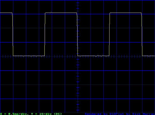
Here, for example, I'm looking at something being output from my radio.
A serial port.
Now we can see there's a definite pattern to those wibbles. So let's bring it into RISC OS for a closer look.
The captured waveform.
Much better. But we can do more with this.
The timebase is 20µs/div, and it looks like the signals last for about half of that. Well, okay, could this be a serial signal? Possibly. But how fast does serial go? The simple way to get an idea is to divide one by the baud rate. We'll start with 115,200 as this is very common these days.
>PRINT 1 / 115200
8.68055556E-6
>
Okay, that's not so helpful. Let's bash BASIC a little to get a reply that normal people can understand.
>@% = "F.8"
>PRINT 1 / 115200
0.00000868
>
Okay, you can see that the '868' comes after five zeros. There are a million microseconds in a second, and this value of five zeros and 868 means 8.6 millionths of a second. Which is better expressed as 8.6µs.
Which means that each bit should take a little under half of a square.
Which seems to be the case.
But we can do a little more. You see the little lines? Well, in the 20µs/div setting, each one represents 4µs, so two of them (more or less) should equate to be a bit.
If the protocol is 8N1 (also typical), we'll have a low start bit, followed by eight highs (0) or lows (1), followed by a high stop bit... and that sort-of looks like that we can see.
As it happens, I already knew this having done the work previously, but I thought I'd repeat it so you can see the process in action.
And now, you can examine these waveforms in RISC OS, and have nice tidy images (Paint can export PNGs) for use on websites or documents or whatever.
Not bad for a morning's work. Writing this blog article took rather longer than writing and debugging the code. ☺
But, then, it's raining outside and - FFS - starting to get dark and it isn't even six yet. Winter sucks giant hairy donkey balls.
Please note that while I check this page every so often, I am not able to control what users write; therefore I disclaim all liability for unpleasant and/or infringing and/or defamatory material. Undesired content will be removed as soon as it is noticed. By leaving a comment, you agree not to post material that is illegal or in bad taste, and you should be aware that the time and your IP address are both recorded, should it be necessary to find out who you are. Oh, and don't bother trying to inline HTML. I'm not that stupid! ☺ ADDING COMMENTS DOES NOT WORK IF READING TRANSLATED VERSIONS.
You can now follow comment additions with the comment RSS feed. This is distinct from the b.log RSS feed, so you can subscribe to one or both as you wish.
C Ferris, 30th October 2023, 10:51
Rick have you thought about getting a USB scope
Rob, 31st October 2023, 00:15
The plotted graphs look dreadful on mobile view... ;-)
jgh, 31st October 2023, 16:57
What happens if you get an error in your error handler? The code I use and recommend is: IF in% THEN temp%=in%:in%=0:CLOSE#temp%
Then if an error occurs you won't get cascading attempts to keep cleaning up the error-generating error handler. Similar for "closing" any other resources, eg: da%=da%:IF da%:A%=da%:da%=0:SYS "OS_DynamicArea",1,A% db%=db%:IF db%:A%=db%:db%=0:SYS "OS_Module",7,,A%
Rick, 31st October 2023, 17:41
Colin: I'd be surprised if there are any USB scopes that would work with RISC OS. Hell, do any use a documented protocol?
Rob: Most things look terrible in mobile view. ;) It renders intentionally low quality for those who still pay per megabyte (a lot of pay as you go cards still do that nonsense).
JGH: Good call, but I did say it was lightly tested. On the other hand, setting the handle to zero after closing it would have been halfway smart, wouldn't it? ;)
David Pilling, 31st October 2023, 23:23
Just for info, I don't think it is a serious proposition. I bought the following for 50 quid:
Hantek 6022BE USB Digital Storage Oscilloscope, 48MSa 20MHz / s 2-channel USB virtual oscilloscope, used for laptop computers.
There is open software 'open Hantek' which ISTR I use. Worst thing was loading the USB drivers - ISTR Windows keeps throwing them away.
The situation of third parties having to write software for scopes is quite common. Usual thing of hardware companies being no good at software.
Anyone in possession of a computer with an A2D thinks "I shall produce a 'scope" which is usually a good idea until they get to the software when they get fed up.
One exception may be the BBC Micro. Although I can't recall how slow the A2D was.
The above, grabbing the screen, is a good idea and useful.
I'd imagine others on other platforms have gone beyond - like offering Fourier transform of signals.
Anyway there is pleasure to be had from owning a scope, no matter how narrow the bandwidth.
Interesting that 'scopes were invented at the end of the 1890s.
What else would you want - spectrum analyser, VNA (vector network analyser) (cheap ones are available from usual sources), get all these folk on You Tube who restore HP test gear, desirable if you can be bothered.
This web page is licenced for your personal, private, non-commercial use only. No automated processing by advertising systems is permitted.
RIPA notice: No consent is given for interception of page transmission.