It is the 1508th of March 2020 (aka the 16th of April 2024)
You are 18.222.69.152,
pleased to meet you!
mailto:blog-at-heyrick-dot-eu
Advent 2021 day 7
Mamie Fletcher's House 7
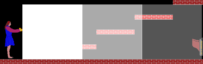
The camera flash
Since a camera is used to dispatch the ghosts, it would make sense to have a visualisation of a camera flash. I decided to simply plot three rectangles of decreasing 'brightness', because it needs to be fast to draw, and it's only on-screen for three frames (a little over 1/30th of a second - indeed it's a flash).
Properly, it ought to start with two triangles, but this is adding complication. And as you'll soon discover, even a simple thing is complicated!
Smile ghost, you're on Candid Camera!
(hmm, looks like the squares are starting and ending on the same column offset, which is why the brighter line is between the two dimmer squares; not really something that would be visible in game play given for how little time it is actually on the screen)
Using a colour table
Since we are working in the VIDC 256 colour mode, we're dealing with a gonzo palette system with four bits per colour stuffed into an eight bit value as follows:
Bit
7
6
5
4
3
2
1
0
Colour
Blue 3
Green 3
Green 2
Red 3
Blue 2
Red 2
Tint 1
Tint 0
The tint bits are bits 0 and 1 of each colour. So if tint 1 is set, then that means red 1, green 1, and blue 1 are all set.
Therefore, I had one table with the lower bits set (red 2, green 2, blue 2, and tint 0). This made some colours slightly brighter.
The next table had the upper bits set (red 3, green 3, blue 3, and tint 1). This made things a lot brighter.
The final table had both bits set, which essentially meant all bits were set, so the result was white.
The basic method of what we're doing
Each square is "up to 200 pixels", with a total flash width of 600 pixels. I say it a little vaguely like this, as the actual flash width is constrained by walls and the door. It would be dumb to be able to fire the flash and get the ghost on the other side of a wall!
Now that we have a width, what remains to be done is to read the screen to see what colours are there, and write back the modified data.
If we reach 200 pixels, switch to the next table and carry on.
If we reach 400 pixels, switch to the final table and carry on.
If we reach 600 pixels, we're done.
Doing it the hard way
The hard way was to read a pixel, look up the replacement colour, and write the pixel back.
I wrote the following code to do this. It isn't at all optimised, but we're a little hamstrung by the need to deal with byte values and a byte lookup table so some of the fancier instructions in later architectures may well not be of much use. It would have flown if it could work with whole words, but needs to work with up to thirty six thousand pixels, up to three times. Worse case? A hundred and ten thousand pixel reads, lookups, and writes.
If you're not a geek, or don't know ARM code, you can either read the comments (the bits in green) to see how it works, or skip this code entirely. Though I did all of the colouring by hand, so please at least appreciate the time it took to do that!
Oh, and yes, it's basically the same thing three times. Scope for optimisation there, but I wanted working code before clever code. ☺
   ; On entry
   ;
   ;  R0 = Which level is this (1-3)
   ;  R1 = Our X position
   ;  R2 = How many pixels to draw (must be correctly clipped!)
   ;  R3 = Colour table
   ;
   ; We calculate
   ;  R4 = Screen base address
   ;  R5 = Starting line address
   ;  R6 = Our current address
   ;  R7 = Which pixel we're plotting (counts DOWN)
   ;  R8 = Which row we're plotting (counts DOWN)
   ;  R9 = Colour byte / temp


   ; Sanitise width
   CMP    R2, #0
   MOVLE  PC, R14             ; signed lower or same

   ; Sanitise X position
   CMP    R1, #SCRWID%
   MOVHS  PC, R14             ; unsigned higher or same

   ; Get the screen base address
   STMFD  R13!, {R0, R1}
   ADR    R0, vduvars
   ADR    R1, vduinfo
   SWI    "XOS_ReadVduVariables"
   ADR    R1, vduinfo
   LDR    R4, [R1]            ; pick up the base address
   LDMFD  R13!, {R0, R1}

   ; Work out line address from which level we're on
   ADR    R9, startlines
   LDR    R5, [R9, R0, LSL#2] ; get the start line offset
   ADD    R5, R5, R4          ; then add in the base address

   ; Do we have more than 200 pixels to plot?
   CMP    R2, #200
   MOVHS  R7, #200            ; yes, so do the first 200
   MOVLO  R7, R2              ; no, so record how many are to be plotted

   ; Right... in order to reduce the number of comparisons, we will
   ; plot the bright part, then the midrange part, then the dimmer part.

   MOV    R8, #(LVLHEI% - 13) ; how many rows to plot
.brightrows
   ADD    R6, R5, R1          ; position = line address + x offset

.brightpixels
   LDRB   R9, [R6]            ; get pixel from the given address
   LDRB   R9, [R3, R9]        ; read the converted bright colour
   STRB   R9, [R6], #1        ; write pixel back to screen, increment offset

   SUBS   R7, R7, #1          ; decrement pixel counter
   BNE    brightpixels        ; loop if more to do

   ; A line has been done, so move to the next line up
   SUB    R5, R5, #SCRWID%    ; back a line

   CMP    R2, #200            ; recalc the number of pixels to plot (saves a register)
   MOVHS  R7, #200            ; yes, so do the first 200
   MOVLO  R7, R2              ; no, so record how many are to be plotted

   SUBS   R8, R8, #1          ; decrement row counter
   BNE    brightrows          ; loop if more to do


   ; Still more to do?
   CMP    R2, #200
   MOVLO  PC, R14             ; we're done here.


   ; Now we move on to the middle-intensity rows
   ADD    R1, R1, #200        ; 200 pixels to the right
   SUB    R2, R2, #200        ; 200 pixels less to draw
   ADD    R3, R3, #256        ; the next set of colour lookup values


   ; Work out line address from which level we're on
   ADR    R9, startlines
   LDR    R5, [R9, R0, LSL#2] ; get the start line offset
   ADD    R5, R5, R4          ; then add in the base address

   ; Do we have more than 200 pixels to plot?
   CMP    R2, #200
   MOVHS  R7, #200            ; yes, so do the first 200
   MOVLO  R7, R2              ; no, so record how many are to be plotted

   MOV    R8, #(LVLHEI% - 13) ; how many rows to plot
.midrows
   ADD    R6, R5, R1          ; position = line address + x offset

.midpixels
   LDRB   R9, [R6]            ; get pixel from the given address
   LDRB   R9, [R3, R9]        ; read the converted mid colour
   STRB   R9, [R6], #1        ; write pixel back to screen, increment offset

   SUBS   R7, R7, #1          ; decrement pixel counter
   BNE    midpixels           ; loop if more to do

   ; A line has been done, so move to the next line up
   SUB    R5, R5, #SCRWID%    ; back a line

   CMP    R2, #200            ; recalc the number of pixels to plot (saves a register)
   MOVHS  R7, #200            ; yes, so do the first 200
   MOVLO  R7, R2              ; no, so record how many are to be plotted

   SUBS   R8, R8, #1          ; decrement row counter
   BNE    midrows             ; loop if more to do


   ; Still more to do?
   CMP    R2, #200
   MOVLO  PC, R14             ; we're done here.


   ; Finally, the dim rows

   ADD    R1, R1, #200        ; 200 pixels to the right
   SUB    R2, R2, #200        ; 200 pixels less to draw
   ADD    R3, R3, #256        ; the final set of colour lookup values


   ; Work out line address from which level we're on
   ADR    R9, startlines
   LDR    R5, [R9, R0, LSL#2] ; get the start line offset
   ADD    R5, R5, R4          ; then add in the base address

   ; Do we have more than 200 pixels to plot?
   ; ##TODO## Really? Why not just MOV R7, R2?
   CMP    R2, #200
   MOVHS  R7, #200            ; yes, so do the first 200
   MOVLO  R7, R2              ; no, so record how many are to be plotted

   MOV    R8, #(LVLHEI% - 13) ; how many rows to plot
.dimrows
   ADD    R6, R5, R1          ; position = line address + x offset

.dimpixels
   LDRB   R9, [R6]            ; get pixel from the given address
   LDRB   R9, [R3, R9]        ; look up the converted dim colour
   STRB   R9, [R6], #1        ; write pixel back to screen, increment offset

   SUBS   R7, R7, #1          ; decrement pixel counter
   BNE    dimpixels           ; loop if more to do

   ; A line has been done, so move to the next line up
   SUB    R5, R5, #SCRWID%    ; back a line

   CMP    R2, #200            ; recalc the number of pixels to plot (saves a register)
   MOVHS  R7, #200            ; yes, so do the first 200
   MOVLO  R7, R2              ; no, so record how many are to be plotted

   SUBS   R8, R8, #1          ; decrement row counter
   BNE    dimrows             ; loop if more to do


   ; Now exit, as all flash squares have been drawn.
   MOV    PC, R14             ; drop out now, we're done


.startlines
   EQUD   0
   EQUD   ((SCRHEI% -                  13 ) * SCRWID%)  ; bottom line
   EQUD   ((SCRHEI% - ( LVLHEI%      + 13)) * SCRWID%)  ; middle line
   EQUD   ((SCRHEI% - ((LVLHEI% * 2) + 13)) * SCRWID%)  ; top line

.vduvars
   EQUD   148                 ; ScreenStart
   EQUD   -1

.vduinfo
   EQUD   0
   EQUD   0
Of course, it's a bloody nightmare to look at a wodge of assembler when thinking about writing the game in C. Should I translate this code to ObjAsm format and link it in, or should I attempt to rewrite it in C and let the compiler do some magic?
This isn't to say that this code is problem free. On the ROOL forum, Gerph said "And going straight to directly manipulating the screen is terrible from the perspective of making code that works well across the board on many platforms.".
This is a very good point, as while it is fairly generic ARM code, it was not 'scheduled' in any manner, so you might end up with something that is actually rather suboptimal.
To put this into practice, let's look at the core of the pixel update. It is this:
What we're doing here is working out the address of the pixel we want to fiddle with (R6). Then we byte-load the data (into R9). Using a table base address (R3), we use the pixel value (R9) as an offset into that table (R3) to byte-read the new colour. In order words, we read the new colour from R3+R9 (or table plus offset). This value is loaded into R9, which is then written back to the screen (R6).
Simple, right? ☺
Well, let's see how screwed this code is when running on a dual-issue ARM core, such as the Cortex-A8...
Cycle   Pipeline 0                          Pipeline 1
================================================================================
     1  ADD r6,r5,r1                        wait for r6
     2  wait for r6                         wait for r6
     3  LDRB r9,[r6]                        LS unit busy, output conflict, wait for r9
     4  wait for r9                         wait for r9
     5  wait for r9                         wait for r9
     6  LDRB r9,[r3,r9]                     LS unit busy, wait for r9
     7  STRB r9,[r6],#1
That's pretty bad. Essentially, due to waiting and conflicts, it only makes use of the one pipeline. Four instructions, thirteen cycles, nine of them essentially wasted.
Now imagine the waiting on a single pipeline processor...
It wouldn't, actually, make any difference to load the looked up colour into a different register. The first LDRB has a long wait state for R9. It's that that we're mainly waiting for here.
A typical way around this is to perform other operations in the mean time.
To make this point, I have examined the following code:
Cycle   Pipeline 0                          Pipeline 1
================================================================================
     1  ADD r6,r5,r1                        wait for r6
     2  wait for r6                         wait for r6
     3  LDRB r9,[r6]                        ADD r0,r1,r2
     4  SUB r7,r4,r5                        ADD r10,r11,#44
     5  SUB r0,r12,#22                      wait for r9
     6  LDRB r8,[r3,r9]                     LS unit busy, wait for r8
     7  STRB r8,[r6]
Yup. By careful use of registers (you'll notice that none of the new code uses any of the same registers in subsequent instructions), the execution can be spread between the two pipelines so rather than stalling waiting for R9, it can get on with doing other stuff.
But, as you can imagine, scheduling sensibly is really difficult to figure out, not to mention that what works well for one core might not be so great on another...so this is the sort of thing that is best left to a compiler, and it is yet another reason why no sane person writes random stuff in assembler in the twenty first century!
The easy way
In that same forum discussion, Gerph mentioned the bloody obvious (that hadn't occurred to me, hic!) - "In the specific case where you’re working with a 256 colour mode data only, the table you built is essentially a pixel translation table, so using a sprite operation means one call with all the code having already been written (and JIT’d for just your case).
Which... uh... yeah. Was about right. It was a translation table, wasn't it?
So the C code is a lot simpler. It calls OS_SpriteOp 16 to grab a part of the screen (maximum 200×200) as a new sprite. This is then plotted right back again using the lookup table to translate the colours.
The code is better written, using an outer loop working out how much to actually plot, so the same thing isn't repeated three times.
Yup, much better.
Test SpriteOp code in BASIC took about the same time as my assembler code (about 3½ seconds to draw it a hundred times), so while the OS routines aren't especially faster, they aren't slower either. In the actual C version of the game, I haven't benchmarked it at all, but it'll go faster as it won't be interpreting BASIC, nor looking up the SWI name, nor setting up the environment for a SWI call as BASIC does.
What the hell?
I bet you didn't imagine that a simple little visual effect that's visible for a mere blink of an eye took so much effort. That's the thing, though. Mamie Fletcher's House is a collection of all sorts of "little things" that took more thought and consideration than might seem apparent.
This is, perhaps, exaggerated by the fact that there's no game design framework or library for RISC OS. There is the AmCog Game Development Kit, which will get you started with writing games in BASIC, but since this game is in C...
Okay, tomorrow I'll talk about my brilliant beta testers.
Your comments:
Please note that while I check this page every so often, I am not able to control what users write; therefore I disclaim all liability for unpleasant and/or infringing and/or defamatory material. Undesired content will be removed as soon as it is noticed. By leaving a comment, you agree not to post material that is illegal or in bad taste, and you should be aware that the time and your IP address are both recorded, should it be necessary to find out who you are. Oh, and don't bother trying to inline HTML. I'm not that stupid! ☺ ADDING COMMENTS DOES NOT WORK IF READING TRANSLATED VERSIONS.
You can now follow comment additions with the comment RSS feed. This is distinct from the b.log RSS feed, so you can subscribe to one or both as you wish.
This web page is licenced for your personal, private, non-commercial use only. No automated processing by advertising systems is permitted.
RIPA notice: No consent is given for interception of page transmission.