It is the 1517th of March 2020 (aka the 25th of April 2024)
You are 3.17.150.89,
pleased to meet you!
mailto:blog-at-heyrick-dot-eu
ESP32
Microcontrollers have changed a lot in recent times. First there was the 8051 family. Then the PIC, and the big player right now is the many Cortex-M0 devices.
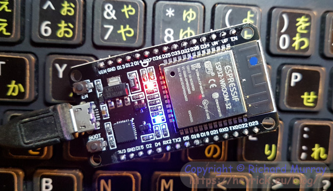
Running in somewhere between the microcontroller and fully blown processor/system-on-chip is this:
It is an ESP32-WROOM-32 module mounted on a development board. The basic specifications of the ESP32 module is a dual core (Xtensa LX6) clocking from 80MHz to a maximum of 240MHz. There's also a low power processor that can do simpler tasks while the main cores are suspended (for enhanced battery life). The main processor has 448KiB internal ROM (for booting and core functions), 520KiB internal SRAM, The WROOM-32 module adds 4MiB SPI flash. There are a number of GPIO pins that offer the usual selection of serial ports (3), ADC (12!), DAC (2), SPI (3), IIC (2), IIS (2), digital I/O, PWM, et cetera.
But what makes this device different is that it also contains an onboard WiFi transceiver supporting 802.11 b/g/n (upto 150Mbps) in the 2.4GHz bands. There's also a Bluetooth Br/EDR/BLE transceiver as well, but it's the WiFi that is the most interesting.
Did I mention that it's about seven euros? It's like the well known ESP8266 on drugs!
The bigger board breaks out the ESP32's GPIO into something that can be plugged into a stripboard, plus it uses a USB connector to provide power and also to communicate with the ESP32 using UART 0. The ESP32 doesn't have any USB connectivity This is used for programming the device, and also for communicating with it, output for debug messages, etc.
There are also two LEDs. A red one (connected to the power, shows the device is on) and a blue one (user controlled, it's connected to GPIO2). There are two buttons, on the left is one marked EN that is used for rebooting the device, and on the right is one marked BOOT that is used to select boot mode (normal boot, or hold it down to enter programming mode for reading/writing Flash/memory).
It's not a "proper" SoC because it lacks two things that modern operating systems expect. The first is an MMU. The memory mapping is fixed, and both cores can access the same memory. The second is a video driver/GPU. This can be faked by constructing an image of some sort in memory and pushing it out to an attached display, however we're talking small TFTs and OLEDs. It's worth noting that an 8bpp VGA display (640×480) would require 300KiB memory. That's more than half of what's available, not to mention the time taken to push it to the display using SPI. So, no, this isn't for running an operating system. It's intended to sit quietly and 'do stuff', but things a little more complicated than a bread maker. Unless, of course, you wanted a smart bread maker that could report its status (current temperature, etc) and send you an email you when the bread is ready. That, this device could probably do.
First power up
Plugging it in showed a red LED. Installing the serial port driver (if necessary, it's a Silicon Labs CP210x UART) and plugging the board in instantly froze my PC. Turns out that I can't have the ESP32 and my USB WiFi dongle active at the same time. Thankfully I bought a switch for my Vonets, so I just plugged the PC's wired ethernet into that. But if your computer stiffs itself, check that there isn't some sort of clash with other USB devices in use at the same time.
Running HyperTerminal (115200bps, 8 bits, 1 stop bit, no parity, no flow control) showed this:
ets Jun  8 2016 00:22:57

rst:0x1 (POWERON_RESET),boot:0x13 (SPI_FAST_FLASH_BOOT)
configsip: 0, SPIWP:0xee
clk_drv:0x00,q_drv:0x00,d_drv:0x00,cs0_drv:0x00,hd_drv:0x00,wp_drv:0x00
mode:DIO, clock div:2
load:0x3fff0018,len:4
load:0x3fff001c,len:5564
load:0x40078000,len:0
load:0x40078000,len:13756
entry 0x40078fb4
I (28) boot: ESP-IDF v3.0.1 2nd stage bootloader
I (29) boot: compile time 05:26:56
I (29) boot: Enabling RNG early entropy source...
I (33) boot: SPI Speed      : 40MHz
I (37) boot: SPI Mode       : DIO
I (41) boot: SPI Flash Size : 4MB
I (45) boot: Partition Table:
I (49) boot: ## Label            Usage          Type ST Offset   Length
I (56) boot:  0 phy_init         RF data          01 01 0000f000 00001000
I (64) boot:  1 otadata          OTA data         01 00 00010000 00002000
I (71) boot:  2 nvs              WiFi data        01 02 00012000 0000e000
I (79) boot:  3 at_customize     unknown          40 00 00020000 000e0000
I (86) boot:  4 ota_0            OTA app          00 10 00100000 00180000
I (93) boot:  5 ota_1            OTA app          00 11 00280000 00180000
I (101) boot: End of partition table
I (105) boot: No factory image, trying OTA 0
I (110) esp_image: segment 0: paddr=0x00100020 vaddr=0x3f400020 size=0x1fe00 (130560) map
I (165) esp_image: segment 1: paddr=0x0011fe28 vaddr=0x3ffc0000 size=0x001e8 ( 488) load
I (165) esp_image: segment 2: paddr=0x00120018 vaddr=0x400d0018 size=0xddcc0 (908480) map
I (490) esp_image: segment 3: paddr=0x001fdce0 vaddr=0x3ffc01e8 size=0x03010 ( 12304) load
I (495) esp_image: segment 4: paddr=0x00200cf8 vaddr=0x40080000 size=0x00400 (1024) load
I (497) esp_image: segment 5: paddr=0x00201100 vaddr=0x40080400 size=0x0eba0 ( 60320) load
I (530) esp_image: segment 6: paddr=0x0020fca8 vaddr=0x400c0000 size=0x00064 ( 100) load
I (540) boot: Loaded app from partition at offset 0x100000
I (540) boot: Disabling RNG early entropy source...
Bin version(Wroom32):1.1.1
I (658) wifi: wifi firmware version: bffcf7f
I (659) wifi: config NVS flash: enabled
I (659) wifi: config nano formating: disabled
I (668) wifi: Init dynamic tx buffer num: 32
I (669) wifi: Init data frame dynamic rx buffer num: 32
I (669) wifi: Init management frame dynamic rx buffer num: 32
I (675) wifi: wifi driver task: 3ffdf604, prio:23, stack:4096
I (680) wifi: Init static rx buffer num: 10
I (683) wifi: Init dynamic rx buffer num: 32
I (688) wifi: wifi power manager task: 0x3ffe3ce4 prio: 21 tack: 2560
I (721) wifi: mode : softAP (cc:50:e3:8b:ac:ad)
I (728) wifi: mode : sta (cc:50:e3:8b:ac:ac) + softAP (cc:50:e3:8b:ac:ad)
I (732) wifi: mode : softAP (cc:50:e3:8b:ac:ad)
At this point, a new WiFi access point ("ESP_8BACAD") was seen by my phone. I could connect to it, and was assigned an IP address (192.168.4.2), however there was no response at http://192.168.4.1/ (the AP/gateway address), nor did the device respond to any commands given to it.
Interestingly, Colin (RISC OS forum) ordered one that seemed to have an older firmware (responded to some commands and didn't have SoftAP). My firmware appears to have been expected to respond to AT commands given over the serial port, but for some reason this appears to have been be a different serial port than the one the computer would have been plugged into. To make matters worse, it looks as if the choice of which serial port to use is baked in at OS build time, rather than doing something clever like having it start off as the same port, and having an AT command to reassign it (so one could, you know, set the device up after flashing it!).
A brief foray into Lua
I discovered LoBo Lua and flashed that into the device. This was actually quite nice, it seemed. It talked to the serial port, it offered a small SPIFFS filing system to save programs on flash, it would run an "autorun" script at boot...
ets Jun  8 2016 00:22:57

rst:0x1 (POWERON_RESET),boot:0x13 (SPI_FAST_FLASH_BOOT)
[...snip...]
I (101) boot: Partition Table:
I (113) boot: ## Label            Usage          Type ST Offset   Length
I (135) boot:  0 nvs              WiFi data        01 02 00009000 00006000
I (159) boot:  1 phy_init         RF data          01 01 0000f000 00001000
I (182) boot:  2 factory          factory app      00 00 00010000 00100000
I (205) boot: End of partition table
I (218) boot: Disabling RNG early entropy source...
I (235) boot: Loading app partition at offset 00010000
[...snip...]
I (1636) heap_alloc_caps: Initializing. RAM available for dynamic allocation:
I (1658) heap_alloc_caps: At 3FFBE128 len 00021ED8 (135 KiB): DRAM
I (1679) heap_alloc_caps: At 3FFE8000 len 00018000 (96 KiB): D/IRAM
I (1700) heap_alloc_caps: At 4009E408 len 00001BF8 (6 KiB): IRAM
I (1721) cpu_start: Pro cpu up.
I (1733) cpu_start: Starting app cpu, entry point is 0x40080e18
I (0) cpu_start: App cpu up.
I (1764) cpu_start: Pro cpu start user code
I (1821) cpu_start: Starting scheduler on PRO CPU.
I (72) cpu_start: Starting scheduler on APP CPU.

--------------------
Booting Lua RTOS...

 Boot reason: Vbat power on reset
Time not set: build time: Wed Mar 15 16:30:19 2017

  /\       /\
 /  \_____/  \
/_____________\
W H I T E C A T

Lua RTOS LoBo 0.2 build 1489595419 Copyright (C) 2015 - 2017 whitecatboard.org
board type ESP32 THING
cpu ESP32 rev 1 at 240 Mhz
flash EUI 5059821224a26258
spiffs0 start address at 0x180000, size 1024 Kb
spiffs0 mounted
Mounting SD Card: Failed to initialize. Check connection.

can't redirect console messages to file system, an SDCARD is needed

Lua RTOS LoBo 0.2 powered by Lua 5.3.4

Executing /autorun.lua ...
I (371) phy: phy_version: 329, Feb 22 2017, 15:58:07, 0, 0
SYSTEM_EVENT_STA_START
SYSTEM_EVENT_STA_DISCONNECTED
SYSTEM_EVENT_STA_CONNECTED
SYSTEM_EVENT_STA_GOT_IP

/ >
Getting stuff done was really quite easy - my startup was:
-- Connect to the Livebox
-- (use net.wf.scan() to read APs)
net.wf.setup(net.wf.mode.STA, "Livebox-XXXX", "BigLongPasswordHere")
net.wf.start()

-- get the current time (but read it how?)
net.service.sntp.start()

-- switch on blue LED to indicate the system is up
-- (probably ought to error check stuff, but it'll bomb out early if problem)
pio.pin.setdir(pio.OUTPUT, pio.GPIO2)
pio.pin.sethigh(pio.GPIO2)
And there was even a VT100 style full screen editor built in.
But I had to ditch this.
Why?
Because starting the http server service would crash the ESP32 (registers, backtrace, halt). Useful...
So close, yet so far...
Arduino IDE
It seemed as if everything available for the ESP32 (Espressif's own IDE) was built for later versions of Windows than XP. It wasn't terribly helpful in that all this stuff just said "Windows", didn't even specify if 32 bit or 64 bit...
The Ardunio IDE works on XP. I think it's actually a Java-based toolkit (write once, run everywhere) but this makes it incredibly slow. We're looking at around five minutes to build a small program on a 2.4GHz XP box.
Unfortunately, the ESP32 additions are not compatible with XP. Your build will start, and then fail with weird errors that look like they might have something to do with Python.
So...
Installing Arduino IDE ESP32 on XP
Install the the serial driver if you don't already have it (or another way of talking to your board).
Install the Arduino IDE (I used the Windows installer version).
Don't run it yet. Open the IDE's folder (probably C:\arduino-1.8.8) and create a folder in there called "portable".
This will cause the IDE to place extra definitions and settings there, instead of buried deep in the mess that is "Documents and Settings".
Run the IDE. Go put the kettle on while it starts up.
In the File menu, choose Preferences.
In the window that opens, down the bottom is a long writeable icon marked "Additional Boards Manager URLs".
In there, write: https://dl.espressif.com/dl/package_esp32_index.json
Click OK.
In the Tools menu, go down the the "Board" option (the first one with submenus), it'll probably be some sort of Arduino listed. Open the submenu and click on "Boards Manager...".
Wait for it to update.
In the "Filter your search" part at the top, enter ESP and you'll see it'll come up with an entry saying "esp32 by Espressif Systems version 1.0.1" (or the like).
Install that. It's pretty big (about 155MiB), so go put the kettle on again.
When the board has been installed, go back to the Tools menu and open the Board menu and pick "ESP32 Dev Module". If you purchased a different ESP32, like the DOIT board, choose that instead. The Dev module is for the cheap clones you'll find on eBay, Amazon, etc.
The rest of the stuff can be left at defaults for now: upload at 115200, 160MHz CPU, flash 40MHz DIO 4MB...
The only other thing to do is to set the port to the applicable COM port.
When you have done this, open the serial monitor, set the speed to 115200 baud, then press the EN button on the ESP32.
You should see output as it boots.
Now shut down the Arduino IDE, we have to hack it...
Install Python 2.7, ensure it goes in C:\Python27.
Yes, I know it's nearly a decade out of date. Stuff refers to version 2.7, so best to install what it expects.
You will need PySerial, however newer versions are not XP compatible (refers to unknown API call "CancelIoEx"). So I installed the oldest version of PySerial available.
It works, but it's a pre-release build. You might want to experiment to see if a later one works for you?
Here is the PySerial installer that I used (v3.0a0). It'll install itself into Python.
Now the hard part.
Using an editor that understands LF terminated files (in other words, NOT Notepad!), load the file C:\arduino-1.8.8\portable\packages\esp32\hardware\esp32\1.0.1\platform.txt.
What we're going to do is remove references to the prebuilt executables, and instead run the Python code directly.
At the top, you'll see a number of lines beginning "tools.", followed by lines beginning "compiler.".
In the "tools." lines, look at the ends of the lines for references to ".exe" and change those to ".py". There should be three of them (esptool.exe, espota.exe, and gen_esp32part.exe).
Search for "create eprom". You will see the next line begins: recipe.objcopy.eep.pattern={tools.gen_esp32part.cmd} [etc]
Change this to:
recipe.objcopy.ee.pattern=c:\python27\python {tools.gen_esp32part.cmd} [etc]
That is to say, insert "c:\python27\python " between the "pattern=" and the opening curly brace.
Go down a few lines to the "create hex" entry, and do the same thing here.
Finally, at the end are two lines for "tools.esptool_py.upload.pattern". We want the one that isn't Linux. Insert the call to Python here as well.
Save the updated Platform file.
We're not done yet, one more thing...
Copy C:\arduino-1.8.8\portable\packages\esp32\hardware\esp32\1.0.1\tools\esptool.py into the folder C:\arduino-1.8.8\portable\packages\esp32\tools\esptool_py\2.6.0.
I have no idea why this program is in a different place, but that's how it is. Put the python source in there...
Open a command window in the folder containing esptool.py (if you don't have that tool available, you'll need to CD to that folder.
Connect the ESP32.
Enter: esptool.py -p COM5 chip_id (replace COM5 with whatever is appropriate for your machine).
Problem solver:
esptool doesn't run - was Python installed correctly?
esptool runs, then bails with an error about CancelIoEx - downgrade to an older PySerial.
esptool runs, then bails with lots of stuff that looks like missing files - was PySerial installed correctly?
esptool runs but can't connect to the ESP32 - correct COM port specified?
esptool can't connect, COM port correct - you may need to hold down the BOOT button until esptool connects. Just hold it and be patient.
You should have something saying your chip is an ESP32D0WDQ6, listing its features, then it's MAC address. Something about uploading and running a stub, then a warning that there is no chip ID so it'll return the MAC instead.
Actually doing something
Start the Arduino IDE.
In the File menu, go to Examples, then ESP32, then AnalogOut, and choose LEDCSoftwareFade.
At the top of the window are two faded looking round buttons, a tick and a right pointing arrow.
Hover over the tick (it'll say "Verify") and click it. This will compile the "sketch" (in Arduino parlance, programs are called sketches for some reason). Don't put the kettle on. Book yourself a flight to India, go, find a tea plantation, wait for the tea leaves to sprout, pick them, fly back, and then put the kettle on. It's really slow.
At the end you should see something about how much memory the sketch uses. It seems to use insane amounts of space. 192K to blink an LED...
If you see text in orange, something went wrong.
When you are ready to upload your compiled sketch program, click on the second round icon, the right-facing arrow (it'll say upload). It'll take a while to get going. When you see the orange messages about trying to communicate with the ESP32, it's probably time to reach up and hold down the BOOT button. Don't worry if it freezes on uploading 3% or somesuch, there's more output below. Just wait until you see it say "Hard resetting via RTS pin...". Then you'll know the program has been flashed to the device.
Documentation?
Something that I noticed is that while the Arduino stuff seems to be fairly well documented, the ESP32 extensions are rather less so. There's a lot of stuff buried in random blogs and articles, and I would imagine possibly in numerous deeply buried header files. But if you look online for things like how to read the onboard temperature sensor, you will find the magic incantations, but... is there an easy to digest list of this stuff around?
I presume things will improve. The ESP32 is fairly new (why you won't find many books about it) so maybe better resources will come in time. I think perhaps another problem is that there are two different programming IDEs (Arduino and the Espressif IDF), not to mention a variety of additional language firmwares - I'm aware of Lua and... PicoPython? Something like that.
At any rate, for a cheap but reasonably powerful device for "making smart stuff", it's worth considering the ESP32. It's a little more expensive than a Pi Zero but quite a bit less than a Pi (normal). However, it's small number of I/O pins have many possible functions and it runs code backed into an onboard flash, so it's always ready to go. The RTOS boots in no time - your program will be going in way under a second. The WiFi is also extremely quick to connect, and having WiFi/Bluetooth creates interesting possibilities for remote non-wired control, and also for the device to talk to the outside world.
Something I threw together
I patched together some simple web server code I found online, with the wobbling LED code, to create a server that tells how long it has been running, and the current time, as well as pulsing the LED when connected to WiFi. This one comes to 777974 bytes (59%) of program storage space. Actually, the problem here isn't so much the size of the compiled code, but all the libraries that are included. Looking at the binary in a dump, it seems to me that there's a ton of bloat, such as "/Users/ficeto/Desktop/ESP32/ESP32/esp-idf-public/components/tcpip_adapter/tcpip_adapter_lwip.c" - why on earth does a compiled binary include all the paths?
Then, it contains multiple messages like "(Cannot use WRITE_PERI_REG for DPORT registers use DPORT_WRITE_PERI_REG)" && (!((((((0x3ff42000 + (((1)<1) ? (((1)* 0x1000) + 0x20000) : (((~(1)) & 1)* 0x1000 ))) + 0x80) + i * 4)) >= 0x3ff00000) && ((((0x3ff42000 + (((1)<1) ? (((1)* 0x1000) + 0x20000) : (((~(1)) & 1)* 0x1000 ))) + 0x80) + i * 4)) >= 0x3ff13FFC)) for every single time this sort of thing happens. There're 39 such messages.
Having said that, I can connect to WiFi by giving an SSID and password. I can run a webserver by telling it what function to call to output upon a specific URI, and then just "starting" the service. I guess this is the price you pay for libraries that look after everything for you.
Here's the code I put together, and you can see it in action (at the moment) if you visit http://heyrick.ddns.net:81/.
Copy-paste this into the Arduino IDE to get started...
// Rick's simple server v0.01
// 2019/01/18
//
// Uses LED pulse code from Arduino IDE examples (public domain), and other
// code culled from all over the place. Yay Google. ;-)
//
// Add the libraries we need
#include <WiFi.h>
#include <WiFiClient.h>
#include <WebServer.h>
#include <ESPmDNS.h>
#include "time.h"
// For reading the temperature sensor
extern "C"
{
uint8_t temprature_sens_read(); // typo intentional! ;-)
}
// Define the AP's credentials (hardcoded)
const char *ssid = "Livebox-XXXX";
const char *password = "YOUR_PASSWORD_HERE";
// NTP settings
const char* ntpserver = "pool.ntp.org";
const long gmtoffset = 3600; // CET +1h (3600 seconds)
const int daylightoffset = 7200; // CEST +2h (7200 seconds)
// Create a webserver instance to use port 80
WebServer server(80);
// Set up definitions for LED pulse (channel 0, 13 bit precision, 5000Hz)
#define LEDC_CHANNEL_0 0
#define LEDC_TIMER_13_BIT 13
#define LEDC_BASE_FREQ 5000
// The LED in question is the built-in blue LED
#define LED_PIN 2
// Globals for the LED behaviour
int brightness = 0; // how bright the LED is
int fadeamount = 5; // how many points to fade the LED by
int ledactive = 0; // whether or not the LED is active
// Global counters
int visitcount = 0; // how many views?
int resetcount = 0; // kick a reset?
// Function to behave like "analogWrite"
void ledcAnalogWrite(uint8_t channel, uint32_t value, uint32_t valueMax = 255)
{
// calculate duty, 8191 from 2 ^ 13 - 1
uint32_t duty = (8191 / valueMax) * min(value, valueMax);
// write duty to LEDC
ledcWrite(channel, duty);
}
// HTTP /
void handleslash()
{
// Function to handle HTTP request for '/'
char uptime[32];
char mytime[64];
char temps[64];
char bored[32];
int secs = (millis() / 1000); // get the system uptime directly
int mins = (secs / 60);
int hours = mins / 60;
int days = (hours / 24);
struct tm timeinfo;
uint8_t tempf;
float tempc;
String reply = "<!DOCTYPE html>\n";
// Build uptime string
snprintf(uptime, 64, "%dd, %2dh, %02dm, %02ds", days, (hours % 24), (mins % 60), (secs % 60));
// Try to read the time
if( !getLocalTime(&timeinfo) )
{
// Failed
snprintf(mytime, 64, "< unable to read time >");
}
else
{
// Worked, so let's output a string in the form "Monday, 37 March 2910, 16:44:20"
strftime(mytime, 64, "%A, %d %B %Y, %H:%M:%S", &timeinfo);
}
// Read "temprature"!
tempf = temprature_sens_read(); // bloody fahrenheit!
tempc = (( tempf - 32 ) / 1.8);
snprintf(temps, 64, "%0.2f°C (%dF)", tempc, tempf);
// Bored people
visitcount += 1;
snprintf(bored, 32, "%d bored %s", visitcount, ( (visitcount == 1) ? "person" : "people") );
// Now build up the page using a cool BASIC-like string concatenation ;-)
reply += "<html>\n<head>\n <title>Rick's ESP32</title>\n";
reply += " <style>\n body { background-color: #90EE90; font-family: \"Times New Roman\", times, serif; }\n";
reply += " </style>\n</head>\n\n<body>\n<h2 style=\"color: darkgreen;\">Rick's ESP32</h2>\n\n";
reply += "<table border=\"0\">\n";
reply += " <tr><td align=\"right\">System uptime</td><td>→</td><td>";
reply += uptime;
reply += "</td></tr>\n";
reply += " <tr><td align=\"right\">Local time</td><td>→</td><td>";
reply += mytime;
reply += "</td></tr>\n";
reply += " <tr><td align=\"right\">Core temperature</td><td>→</td><td>";
reply += temps;
reply += "</td></tr>\n";
reply += "</table>\n\n";
reply += "<small><i>This page has been looked at by ";
reply += bored;
reply += ", including you.</i></small>\n";
reply += "</body>\n</html>\n";
// And send it to the user
server.setContentLength(reply.length());
server.send(200, "text/html", reply);
}
void handlefourohfour()
{
// Deal with file not found - just hand back a really simple "oops" message
String message = "OH NO! Four Oh Four!\n\n";
message += "The URI ";
message += server.uri();
message += " doesn't exist. Sorry...\n\n";
server.send(404, "text/plain", message);
}
void setup(void)
{
// Setup timer and attach timer to the LED pin
ledcSetup(LEDC_CHANNEL_0, LEDC_BASE_FREQ, LEDC_TIMER_13_BIT);
ledcAttachPin(LED_PIN, LEDC_CHANNEL_0);
// Set up the server
Serial.begin(115200);
WiFi.mode(WIFI_STA);
WiFi.begin(ssid, password);
Serial.println("");
// Wait for connection
while (WiFi.status() != WL_CONNECTED)
{
delay(500);
Serial.print(".");
resetcount++;
// Sometimes it just doesn't connect, so if we cycle ten times
// then hit the big friendly red button. This usually works. ;-)
if ( resetcount > 10 )
ESP.restart();
}
// Once connected, give our IP address
Serial.println("");
Serial.print("Connected to ");
Serial.println(ssid);
Serial.print("IP address: ");
Serial.println(WiFi.localIP());
// Start the MDNS service
if (MDNS.begin("esp32"))
{
Serial.println("MDNS responder started");
}
// Initialise the time service
configTime(gmtoffset, daylightoffset, ntpserver);
// Attach events to the server
server.on("/", handleslash);
server.onNotFound(handlefourohfour);
// Start server
server.begin();
Serial.println("HTTP server started");
// Now we can switch on the blue LED
ledactive = 1;
}
// Stuff to run in a loop
void loop(void)
{
// Something for the server to do?
server.handleClient();
// LED activity?
if ( ledactive )
{
ledcAnalogWrite(LEDC_CHANNEL_0, brightness); // set LED brightness
brightness = brightness + fadeamount; // set new brightness for next time
// The maximum LED brightness is 255, but clip it at 150 so it can be seen to
// pulse. It's a bright LED and to be honest there's not a lot of difference
// between 150 and 255, so the LED seems to stall 'on'. So 150 is much better.
if (brightness <= 0 || brightness >= 150)
fadeamount = -fadeamount; // reverse at extremities
}
// Insert a pause so the brightness change isn't insane
delay(80); // 8cs
}
Your comments:
Please note that while I check this page every so often, I am not able to control what users write; therefore I disclaim all liability for unpleasant and/or infringing and/or defamatory material. Undesired content will be removed as soon as it is noticed. By leaving a comment, you agree not to post material that is illegal or in bad taste, and you should be aware that the time and your IP address are both recorded, should it be necessary to find out who you are. Oh, and don't bother trying to inline HTML. I'm not that stupid! ☺ ADDING COMMENTS DOES NOT WORK IF READING TRANSLATED VERSIONS.
You can now follow comment additions with the comment RSS feed. This is distinct from the b.log RSS feed, so you can subscribe to one or both as you wish.
colin, 19th January 2019, 15:08
I figured out how to install the esp-at program onto the device - it's a bit of a faff and you use another serial connection to read/write the AT commands.
Download 'Flash download tools (ESP8266 & ESP32)' from
run 'Downloads\flash_download_tools_v3.6.5_0\flash_download_tools_v3 .6.5\flash_download_tools_v3.6.5\flash_download_tools_v3.6.5.exe '
A window pops up where you select 'ESP32 Download Tool'
Use the 'SPIDownload Tab. Set CrystalFreq = 40M, SPI MODE = DIO and FLASH SIZE = 32Mbit
Goto the Downloads\ESP32_AT_V1.1.3\ESP32_AT_V1.1.3\ESP32_AT_V1.1.3 folder and open download.config in a text file You only want to read it. If you add a newline before every '0x' to make it easier to read you get a file like this
Now in the download tool there is a lot of writable fields at the top with tickboxes next to them. You need to enter the details from download.config into these fields but the filenames need to be full pathnames.
the second [tick] D:\Colin\Downloads\ESP32_AT_V1.1.3\ESP32_AT_V1.1.3\E SP32_AT_V1.1.3\at_customize.bin 0x20000
etc.
Now select START and press 'boot' on the device. It should now put the program on the device.
When the program says FINISH you can reset the device by pressing the 'en' button on the device. You can see output after a reset on the USB coms port but that's not how you interact with the program.
Now you need to connect pin 16 to RX pin 17 TX and you can connect and use the AT commands
If you connect those pins to the Pi serial port my SerialTerminal program should still work with the internal serial ports.
Colin, 19th January 2019, 15:35
Oops I showed the download_config from v1.1.2. v1.1.3 looks like this
factory_param.bin is replaced with factory_param_WROOM-32.bin (the file is dependent on the device)
Rick, 19th January 2019, 23:06
The Flash download tools don't work on XP. ;-) Plus, if you use the Arduino IDE to program, it uses esptool so it might be useful to have some experience of how that works.
Yes, it seems like you have to install the toolchain and rebuild the firmware in order to alter the serial port used for the AT commands. What a pain!
Colin, 20th January 2019, 18:45
Ok the easy version.
Forget about the download tool there's an easier way.
Download ESP32_AT_V1.1.3
Change the directory to the one containing download.config.
flash the device with
esptool.py --port com6 write_flash
with your com port followed by the contents of the download.config file.
I don't know if your version of esptool.py uses a unix style file separator or whether that is a peculiarity of the ESP-SDK if not you may have to change the file separator to a backslash.
I don't use Arduino - I tend to use Pics. I tried Eclipse IDE but it was too much effort - easier to just use notepad++ and the ESP-SDK bash shell - except looking into included files is difficult.
I'm having difficulty compiling esp32-at at the moment. It may be because I'm using a 32bit pc. I think the problem is the python version despite it saying that it has all the python requisites in the makefile output.
Rick, 22nd January 2019, 23:42
The ESP32 is no longer available. I'm (rather unsuccessfully) trying to set it up as a webradio (https://github.com/Edzelf/ESP32-Radio) and the AP mode is broken so if it messes up its configuration (seems prone to do) then it'll require a firmware rebuild after pushing the settings back. All in with the extreme slowness of the Arduino IDE, this takes about an hour. I can't believe I've come across a compiler that could be outpaced by a BBC Micro...
Colin, 23rd January 2019, 11:29
'The ESP32 is no longer available'
I wouldn't miss it but how do you work that out? It's still on the espressif.com website.
I achieved what I got it for, seeing if SerialUSB could access it given your problems, but I find it the worst programming experience I've ever encountered. The ESP windows 32 bit environment doesn't compile their github sources. The toolchain doesn't compile on armbian so I can't even try the using it there. Everything takes *ages* to compile. It's quicker to compile riscos from scratch than compile the 'hello_world' example.
I hope my experience isn't normal I can't believe that anyone would wait half an hour to find out that they had missed the semicolon off the end of printf("hello world\n")
Rick, 23rd January 2019, 11:57
Lesson: don't write messages in a hurry whilst tired.
What I meant was the one at heyrick.ddns.net is no longer there - the link won't work any more.
As for the ESP32 itself, I rather expect it'll do a Pi - sooner or later a faster better specified model will appear. Maybe with onboard USB or something?
Rick, 23rd January 2019, 12:04
"Everything takes *ages* to compile."
This. Ever so much this. They need a simple command line compiler written in something normal like C, runs on everything from a 486 up, easily portable to other systems, reads the source and spits out a binary. In, like, 30 seconds on normal machines. As you point out, it's quicker to build the entirety of RISC OS than anything for the ESP32. Your experience matches mine.
I'm going to ditch the ESP radio and try rolling my own simpler code by piecing stuff together. I don't relish the idea of how long I'll be twiddling my thumbs while it compiles. I guess if it takes about half an hour each time, I can dig out my New Girl DVD set and watch an episode each time...
David Pilling, 28th January 2019, 15:53
A lot of retro ESP32 games machines: https://www.youtube.com/watch?v=9y9BLEu7f0g Arduino is slow, it does not save intermediate files between sessions. ESP compilers always exist somewhere if you have the knowledge to use them. I was never a fan of ESP because of the effort required to use it. Slow as it is, Arduino makes it accessible.
Philippe, 20th February 2019, 18:14
Hi, very interresting, i'm stuck with ESP32 and WXP I follow carefuly your mods, and now it compile. But impossible to upload i got "upload.pattern" is missing. This ESP 32 is working find with Arduino IDE and W10, but i want to use my WXP portable computer on field Thanks for help
David Morphett, 10th June 2019, 04:21
Hi Rick, Just wanted to say thank you a thousand times. I had spent far too many hours trying to get the Arduino IDE to work on XP with ESP32 by following instructions on various web sites including GitHub and Espressif. None of the suggested fixes worked. Fortunately I came across your solution as I was about to give up. Largely followed your exceedingly well written (and entertaining) instructions and success! The only difference was that I didn't go the portable route but edited platform.txt in my C:\Documents and Settings\<me>\Local Settings\Application Data\Arduino15\packages\esp32 .... David
This web page is licenced for your personal, private, non-commercial use only. No automated processing by advertising systems is permitted.
RIPA notice: No consent is given for interception of page transmission.