It is the 1512th of March 2020 (aka the 20th of April 2024)
You are 18.189.180.244,
pleased to meet you!
mailto:blog-at-heyrick-dot-eu
A random Christmas-season-sucks song
The quintessential song of a Christmas sucking hard in so many ways:
On holiday!
That's it. It's been a hard slog, working full time plus numerous six-day weeks since mid August without a break. I now plan to take the next 11 days to do exactly nothing.
Well, mom might have other ideas... ☺
As is traditional, we're allowed to be a little frivolous on our final day of work. Those of us with a sense of humour got santa hats. Mine has gold effect on it, to be a little more blingy than the normal hat. And while you can't see it in the picture, those plastic stars (forehead) light up in turn. It was possibly the best hat of the entire morning shift.
The afternoon shift, however, really pushed the boat out. LEDs with changing patterns, a blue santa hat (WTF?) and my personal favourite was a hat with a strobe in the white bobble. Well, it was probably just another LED, but damn it was bright. Like a camera flash going off twice a second. Now that qualified as being an "epic" santa hat. I noticed she wasn't wearing it after break - perhaps it was a little too epic?
Yeah, it's a selfie... The intent staring and the V-sign? Yup, I'm totally taking the p<cough>............
Once upon a time, they used to release a yearly catalogue with amazing sci-fi covers and packed with ridiculous amounts of information. For example, I knew my TV came from the Hannington transmitter, what frequencies, what power, and what sort of aerial I needed. Okay, you can get all this information on the internet now, but in 1987 it would break the bank to call Prestel, never mind such luxuries as "The Internet". The Maplin catalogue was the go-to source for all sorts of geeky information. Wanna know the pinouts of a 4000 series CMOS hex counter? Look under ICs. Wanna know what black red red gold means? Look under Resistors. Wanna know a metric tonne of basic electronics theory? Read the opening pages (the ones that aren't trying to sell stuff).
Then along came the '90s and Maplin released a CD-ROM catalogue that was... horrible. I know, I think I still have mine in a box someplace, unless I used it as a bird scarer? The paper catalogue changed. And not for the better. All that information, which was repeated in each catalogue, was thrown away and replaced by padding out the catalogue by having the same things appear under multiple categories (as a made-up example: imagine the same USB harddisc listed under "computers" and "storage" and "information technology", you get the idea).
This was part of the great dumbing down of Maplin. Tandy, the sort of high street rival had pretty much given up on anything that resembled electronics to punt phones and HiFi units. And Maplin seemed to be heading that way. The stores, that used to have shelves of components and staff that knew what those little things were for, seemed to be heading into a sort of "what Tandy was" with staff that could tell you...exactly what was written on the product information card. And whose idea of "a good audio system" was largely defined by simply cranking up the volume. Though, too be fair, everybody was at it - you can easily tell an audio CD mastered in the late '80s and early '90s because it has a good dynamic range, versus those of the mid '90s when range was crap and simply BEING LOUDER THAN EVERYTHING ELSE is what defined a CD. In other words, about a decade's worth of disgusting mixes that should only be inflicted onto the eardrums of people that still persist in listening to 128kbit joint-stereo MP3 encodings.
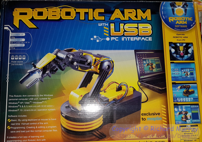
Anyway, Maplin has a robot arm kit - the A37JN Robotic Arm. I happened to notice that there was a short driver program for it on the RISC OS Nano distribution (get the Pico Zip file then extract Examples.NanoArm - it's a simple BASIC program that should work on any modern RISC OS machine).
I also happened to notice that the ARM kit itself was marked down (at time of writing - still is).
So with the help of my friend Mick (and many many thanks for that), he got the kit and posted it over as Maplin have yet to figure out that the rest of the world exists. Oh well, post Brexit that probably won't matter... if they're still around.
Here it is, in an amazingly retro looking box that wouldn't have gone amiss on a shelf back in 1986:
Uh... Save and load just like normal computer files!? (blurb, lower left)
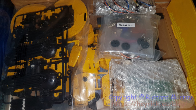
Inside a more woeful story. My God, that's a lot of bits. This is what happens when Airfix meets Meccano...
Still, last year I built myself an insanely fiddly oscilloscope and it worked out okay, so I guess I'll just have to take the slow and careful approach here. So, no, piling all the bits in a heap and hitting them with a large hammer won't build a robot arm. ☺
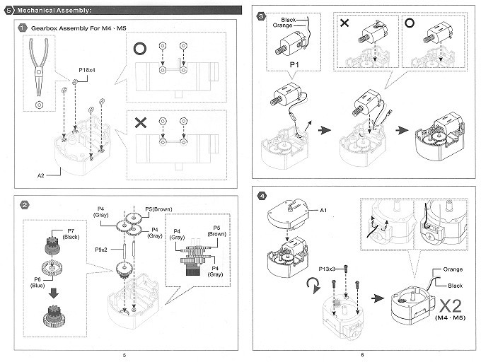
The build instructions are 28 pages of scarily detailed A4 pages, a booklet the contents of which look sort of like this:
I'm not sure which day I'll put this together. I'm sure there'll be photos and stuff when I do.
As it stands, the "robotic arm" is less of a robotic arm and more a remote controlled arm. It is lacking one very important thing - positional sensing. Looking at the instructions and the various bits inside the box, it's basically a set of motors hooked to gears. The motors are controlled by some sort of controller device. In essence, controlling the arm via computer is going to be a real-time process, with "scripted" commands relying on nothing more than timing, which could be rather interesting as the kit runs from four D cells which will have the effect of motor speed depending upon battery level (though I suspect I might rig up a 6V 3V (see below!) power supply instead), not to mention slew in the gearing, timing delays, etc etc.
In other words, it is a toy.
But as anybody who ever owned a BigTrak (not me, sadly) will tell you, that something is a toy doesn't mean you can't have some fun with it as an adult, like this, for the BigTrak. Oh, and you Millennials - keep flicking on through the pages until you get to the harddisc advert (p65). Check your bladder control when you realise that not only was $3,695 a ton of money back then (inflation adjusted, you're looking at around $30,000!), but that price is for a ten megabyte harddisc. As in the storage capacity of about eight floppy discs. Your modern terabyte harddisc? Roughly 100,000 times more capacity for about 1/400th of the cost. The linked magazine is a total blast from the past, and when I was pre-teen, all this stuff was cutting edge!
Where was I? Oh yeah, fun with a toy. Well, two thoughts come to mind:
Adding a grip pressure detector could be difficult. A first thought might be to see about cutting a slot in the grip to embed a microswitch. Another, perhaps more workable, idea would be to realise that the grip closing motor will stall when it can't close any more. This will change the current drawn by the motor (as a DC motor under load draws more current), so a current monitoring device (something like this?) could be employed to detect when the motor has stalled. I'm not sure of the precision of the device, it might be possible to detect how much pressure is being applied by the motor behaviour?
As for the arm positions, we'll need some microswitches to be activated at the end of travel of the various parts of the arm (a "home" position), plus an opto-sensor for each of the motor/gear units. I have a feeling this might require drilling holes into one of the gears, I won't be looking forward to doing that! The opto sensors will operate pretty much like they did in mechanical mice - as the gear turns, light from the LED will be picked up by the sensor, which will make a series of pulses. Counting pulses will give position. It should be fairly accurate, and ridiculously more accurate than just timing the movements (plus accounting for differences in battery capacity). With this in mind, we only need one microswitch per axis, as the number of pulses in a full motion aren't going to change so once the range (say, 600 to rotate the arm 180 degrees on the base) is known, everything can be calibrated from the known values.
Plus, in order to reduce potential cumulative errors of many arm movements, the driver could be made to periodically "home" either the entire arm or a part of it to go back to the known position (perhaps the arm could "park" itself?).
This list is me thinking out loud. That's why there are actually three thoughts, not two as promised. Hey, it's Christmas, you get a free thought! (God help you!). What this does suggest is that removing the current controller and replacing it with something like a cheap STM32 or something in the Arduino family would open up some possibilities.
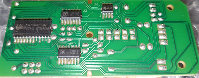
For now... here's the heart of the device (and it must be pretty static-proof given it's just stuck into some buddle-wrap!):
Upper right, an ST1151A (PDF) 1.5 channel motor driver. Don't ask me what one and a half channels means!
The two chips in the middle are both ST1152B (PDF) bi-directional motor drivers. The difference is that this IC can directly control two motors.
The final IC is a weird microcontroller, an EM78M612 (PDF) which seems to be a neat idea, a RISC microcontroller that contains a built-in USB command decoder, so you can concentrate on providing a program to "do something" and not have to worry about implementing and debugging a USB stack. It is an eight bit RISC device with five stacks, eight interrupts, and up to fifteen I/O pins. There's 112 bytes of SRAM, 4 bytes of EEPROM, and the program ROM is 2048 13 bit words (as the instructions are 13 bits long). Actually, it looks like the USB interface extracts the data and serialises it (so it appears as if serial bytes). Due to this, the IC can also interface with a PS/2 port, so I'm guessing this might have been intended for controlling mice and/or keyboards?
Two random observations...
You only need two D cells, not four. Why? The two pads at the bottom right (just left of the hole). That's the black and red from the battery. Notice how one of those pads is connected to... nothing! Yup, that's the red from the battery holder. The orange from the battery? Look above those two pads and you'll see a row of four more from a different connector. And above those, four more. The first terminal of the second set of four is the +ve supply (look carefully, it makes its way down the right edge, across the bottom, and to the switch). So I'll need a 3V supply. Weird...
I hope the LED is a low current type. See the row of five-by-two pins to the right of centre of the board? That's control to four motors and the LED. The LED is the rightmost pair, taking 0V from the 0V rail, and the +ve pin (upper right of the group) apparently being wired directly to the microcontroller without a limiting resistor in sight. So, uh, yeah, that poor microcontroller is sinking the entire current of the LED. Yikes...
Now, if you have not already done so, go press the Play icon up top and enjoy the song. Go on, you know you wanna smirk at You scumbag, you maggot, you cheap lousy faggot, Merry Christmas you arse, and thank God it's our last!
For extra points: Ed Sheeran has recorded this a few times (and murdered the song, IMO), and it's amusing what those lyrics were bowdlerised into to suit modern snowflake tendencies.
Your comments:
Please note that while I check this page every so often, I am not able to control what users write; therefore I disclaim all liability for unpleasant and/or infringing and/or defamatory material. Undesired content will be removed as soon as it is noticed. By leaving a comment, you agree not to post material that is illegal or in bad taste, and you should be aware that the time and your IP address are both recorded, should it be necessary to find out who you are. Oh, and don't bother trying to inline HTML. I'm not that stupid! ☺ ADDING COMMENTS DOES NOT WORK IF READING TRANSLATED VERSIONS.
You can now follow comment additions with the comment RSS feed. This is distinct from the b.log RSS feed, so you can subscribe to one or both as you wish.
David Pilling, 27th December 2017, 03:22
Replacing the motors with steppers would be a solution. Whilst you can get cheap/small ones, unlikely you will find ones that fit. You can get cheap "Opto Interrupters" ITR9606 which are a LED and sensor in a bit of plastic - just like used to be in mice, rotate a disc between them. Good idea to watch the gears go around. Might be fun getting them to stop where you want them. People have looked at the back emf and all the noise from brushed DC motors to decide how they're rotating. For the gripper you could use a strain gauge. RC servos have the same combination of brushed motors and gears, but they use a potentiometer on the mechanical output shaft - all the electronics between the two is super cheap/common. Best memory of Maplin - graphic of Concord(e) on the cover of their early catalogues. Alt reality in which supersonic planes landed at London's third airport in the Thames estuary.
Rob, 9th January 2018, 21:45
Damn. I'm reading your blog posts backwards. So commented on the last (next) one about positional sensors and now find you already had the same idea!..
This web page is licenced for your personal, private, non-commercial use only. No automated processing by advertising systems is permitted.
RIPA notice: No consent is given for interception of page transmission.