It is the 1511th of March 2020 (aka the 19th of April 2024)
You are 3.144.244.44,
pleased to meet you!
mailto:blog-at-heyrick-dot-eu
The DSO 138
I did an unwrapping video. But it was really crap, so I didn't bother uploading it. Suffice to say, what arrived was exactly what I already had. So... yeah... I have a clone DSO138 that arrived this morning, and a clone DSO138 to send back to Amazon... um... <scratches head>
To be honest, I had no real interest in putting this project together today, so I went for a pleasant walk in the fields alongside cows and pheasants...
...yeah. Who am I trying to kid. I set up my soldering iron on the living room table and set to work. There are no "making of" pictures, as I wanted to concentrate completely on building the project. Not only that, but getting it done before I lost the good light.
Making the project actually wasn't that difficult. Fiddly, and tedious with some 200 plus solder joints to make. The only real issue I encountered was my 30W iron wasn't really pumping out enough heat to make good quick connections to the enormous ground plane, and as for soldering the casing of the BNC socket, I'm surprised that it was capable. The official manual reckons you'd need a 20W iron, but do note that a huge number of joints are made to the ground plane, so...
Of course, this doesn't mean get a 60W iron and pump the heat in there. The trick is to solder the component, not incinerate it.
I followed the instructions with respect to the component order, swapping in a 150 ohm resistor for R11 (as is the case with newer boards). Basically start with the little things (the resistors) and work up to the big things.
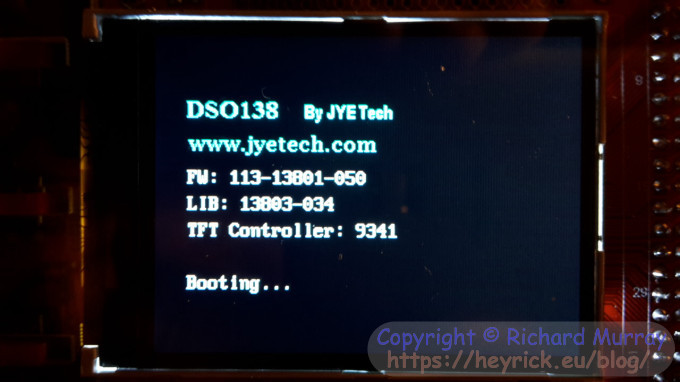
When the main assembly was done, I plugged in the power and tested that about 3.3V was available on the test pin. It was, so I could then short the two pads to send power to the microcontroller, and also plug in the LCD. That done, power up again and...
It isn't the latest firmware, but since updating the firmware is a pain (solder two links, rig up a 3.3V serial connection to the bootloader in the microcontroller, push the data for flashing into the internal 64K memory, then unsolder the two links afterwards...), I'll await the next incarnation.
The hardest part was yet to come. The acrylic case. Provided with no instructions. So I just sort of guessed, and I have a piece left over but everything seems good, so, meh. It'll do.
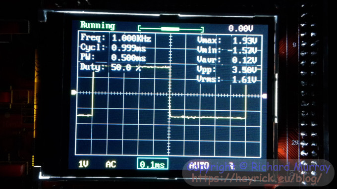
Here is the DSO138 looking at its own test signal, on AC range (though it's a ~3.3V DC pulse) because that puts it in the middle of the display. The test pulse runs at 1kHz and is used for trimming the oscilloscope. Now something that annoys me with traditional oscilloscopes is when you know that each square represents a certain period of time, but converting that into a frequency requires some brainwork. So 0.1ms per square, signal takes five squares on, five squares off, which is 1ms per cycle, with is a thousandth of a second, which is a kilohertz. Fine. That was easy enough, but as you can see from the picture, one just doesn't need to bother with the brain power...
...the signal is 1kHz indeed, 50% duty cycle, pulse width is 500ms, the voltages are read as +1.93V and -1.57V, giving a total of 3.5V.
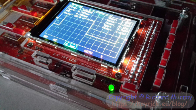
Here is the same activity, this time showing some of the acrylic case:
The three most common options are provided via slide switches, so they are always available. From top to bottom, this is the coupling (GND, AC, or DC). Then comes the voltage sensitivity (1V, 0.1V, 10mV); then finally the sensitivity adjustment (×5, ×2, ×1). The bottom left of the display indicates the volts per square corresponding to the chosen configuration. That is followed by an indication of the coupling.
The rest of the controls are accessed by way of the four buttons on the right. These are OK, +, - and SEL.
OK's behaviour is to switch between Hold (freeze the current waveform) and Run (capture new waveforms). Holding down OK for two seconds will switch the readout on and off. It is worth mentioning that the frequency readout is only available when AC coupled.
The SEL button selects which element of the rest of the user interface is the highlighted part, and then + and - are used to adjust this.
To take a whizz around this, the first element you can select is the timebase. The number in the middle of the bottom of the screen will be outlined in a blue box. You can then use +/- to select 10us, 20us, 50us, 0.1ms, 0.2ms, 0.5ms, 1ms, 2ms, 5ms, 10ms, 20ms, 50ms, 0.1s, 0.2s, 0.5s, 1s, 2s, 5s, 10s, 20s, 50s, 100s, 200s, and finally an astonishing 500s which implies a trace that would take 6,000s (100 minutes!) to cross the screen.
Chances are, in normal use, you'll just leave the highlight on the timebase...
What else is there? Well, the next option is the trigger mode. This can be AUTO (always update the screen regardless of trigger), NORM (update when trigger happens), and SING (single-shot, update when a trigger happens and then automatically hold). That last one would be useful for tracking irregular events.
The next choice is that odd looking arrow thing on the lower right. This, actually, selects whether the trigger is falling edge or rising edge.
Moving on, the highlight goes to the little arrow on the far right of the graticule. This actually sets the trigger level (which is indicated on the upper right). It's a bit fiddly, but useful to know that the oscilloscope remembers its settings. The trigger, by the way, is also visible as a flash of the little green LED. This happens whenever a valid trigger happens, regardless of actual triggering mode. It's only (obviously) inhibited when in HOLD mode.
The next highlight is the bar at the top-centre of the display. This is interesting. When the oscilloscope is in HOLD mode, you can use this to scroll through the recorded samples. When in 0.1ms mode, this equates to about four screenfuls of samples. It is kind of clumsy, and sadly it isn't possible to change the timebase on a frozen waveform to 'zoom' into it - even accepting that this obviously would imply a loss of sample resolution, it might have been nice to expand and contract the saved waveform. But, let's not complain too much, it's pretty impressive for something costing the same as five Happy Meals.
The device also has the ability to save a captured waveform to non-volatile memory (SEL and +) and also to recall the saved waveform (SEL and -) which is kind of neat.
The final part of the user interface is the little arrow on the extreme left. This, when used with the oscilloscope in GND mode, sets the position of the 0V line.
But, like I said, you'll probably be using most of this functionality less, so may well mostly leave the timebase highlighted.
The fifth button? Resets. The device takes about eight seconds to reboot.
Here is an audio signal as presented on the photo plugs from my PVR:
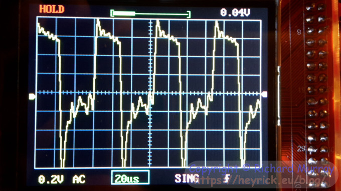
Switching over to the video plug now:
Setting the trigger to -0.7V falling edge displays a fairly steady waveform, though the frequency reading is off because the oscilloscope can 'see' many parts of the signal. Slowing the timebase down to 50us and setting the 0.5V setting with automatic trigger gives a better frequency estimate as the oscilloscope can now mostly see the negative swing of the linesync pulses, with some junk in between. The frequency estimate changes a lot, but the one number you'll see the most us 15.625kHz - which is exactly the PAL line frequency.
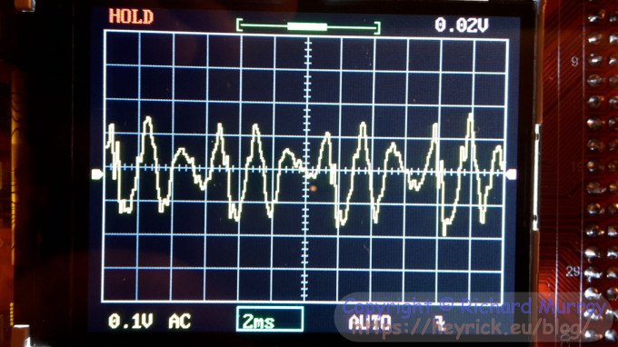
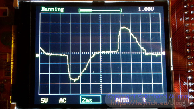
Leaving the ground croc clip disconnected and holding onto the red signal clip gives a very peculiar reading. Now, I am guessing that the signal is 50Hz, induced in me from the mains wiring (heh, and ErDF want to give everybody a flippin' "Linky" smart meter!), but check out the voltage swing - that's 5V per square!
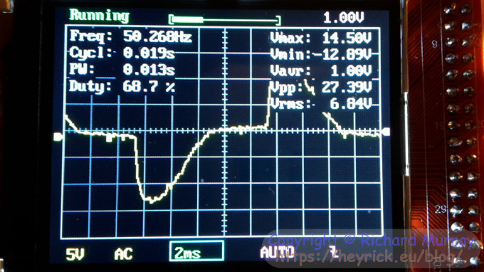
Sure enough, switching on the information readout confirms it:
Conclusion:
While the display isn't particularly high resolution (320×240), it is bright and can be viewed from many angles. The on-screen information has been pared down the that which is necessary, with no extraneous rubbish on-screen - asides from a JYETECH.COM banner with some Chinese characters that pops up for a while every now and then, though this is understandable given the prevalence of clones such as... uh... this one!
The kit wasn't too hard to build really. It took an afternoon. It is worth noting that while I built some Velleman and Maplin kits in my youth, I've not really used a soldering iron for much more than fixing headphones and the like. I think I was a teenager the last time I actually built something electronic.
I'm pleased to report, as you can see from the pictures, that everything went together nicely and the kit booted itself up and started working right away. I have not noticed any weird anomalies (other than the ~30V me!). A signal of X is accordingly sized in the different sensitivity ranges, while the buttons and features work as expected.
There is a very small amount of noise visible at the GND coupling, which is good. Nothing particularly parasitic in the circuit. At the mV setting, with the leads disconnected I'm seeing about 220mV noise at 50Hz, which appears as a slight ripple at the 1V setting. This isn't a surprise, there is an LED lamp, two monitors, several USB power packs (for the Pi, etc), and a whacking great PC all within snails crawl distance of the lead which, let's face it, is going to be acting as an antenna. I think my analogue oscilloscope actually fared worse in this respect. It's just something one has to put up with in an electrically noisy environment.
In short, as much as my analogue oscilloscope is nice, it lacks the convenience of a small box, plus it has many features but waveform capture isn't one of them. It'll be a nice diagnostic tool for looking at the things my multimeter cannot see. It is, of course, limited in its capturing abilities (<200kHz maybe reliably half that), but I think it's pretty impressive for a kit costing the same as five Happy Meals.
Yup. I'm pleased with this.
And I'm dead chuffed it worked first time.
Your comments:
Please note that while I check this page every so often, I am not able to control what users write; therefore I disclaim all liability for unpleasant and/or infringing and/or defamatory material. Undesired content will be removed as soon as it is noticed. By leaving a comment, you agree not to post material that is illegal or in bad taste, and you should be aware that the time and your IP address are both recorded, should it be necessary to find out who you are. Oh, and don't bother trying to inline HTML. I'm not that stupid! ☺ ADDING COMMENTS DOES NOT WORK IF READING TRANSLATED VERSIONS.
You can now follow comment additions with the comment RSS feed. This is distinct from the b.log RSS feed, so you can subscribe to one or both as you wish.
David Pilling, 1st January 2017, 02:58
Well done for getting it to work, lots of people don't. I reckon the mains coupling to you is capacitive. 20V is not unusual if what is doing the measuring has high enough impedance.
This web page is licenced for your personal, private, non-commercial use only. No automated processing by advertising systems is permitted.
RIPA notice: No consent is given for interception of page transmission.