It is the 1512th of March 2020 (aka the 20th of April 2024)
You are 3.21.97.61,
pleased to meet you!
mailto:blog-at-heyrick-dot-eu
Newsflash! Goths are depressed!
A recent study (described here in The Guardian) says that teenage goths are are three times more likely to be clinically depressed blah de blah. In other news, the Pope is Catholic and all men are paedos.
Hey, guys - ever heard of the "perky goth"? If you have difficulty trying to imagine this, think of Abby Sciuto from NCIS. And maybe instead of further stigmatising a group that I'm sure gets plenty of that already, y'all could conduct a study into why depressed goths are depressed? What do they know that you have missed?
More electronics stuff from a vide grenier!
This time last year I purchased an oscilloscope. This time this year, I met the same person and I was prepared with some cash taken out of the bank in advance.
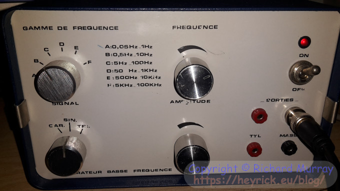
First up - a signal generator for €3. Another piece of school equipment, it claims to output square wave, sine wave, and triangle wave, from 0.05Hz to 200kHz in six overlapping bands. This may be used for providing pulses, or just connecting to a speaker and farting around twiddling the frequency knob for do-it-yourself Doctor Who special effects.
The second range (0.5Hz to 10Hz) does not appear to work. Not sure why (no wires loose inside), but it isn't a big deal. The first range goes up to 1Hz and the third down to 5Hz so I'm only really missing 1Hz-4Hz. Hardly a deal breaker.
The meter is not calibrated. You just select a range and twiddle the knob. More worryingly, the behaviour of the amplitude knob is backwards to the legend - full left is quietest. I'd better make a note of that!
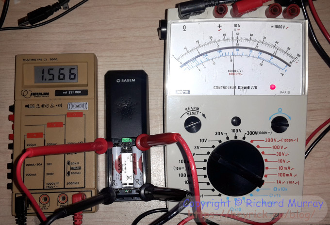
Then two multimeters. A digital one (€3 plus €0,50 for the probes) and an analogue one (€4 with probes thrown in). While there are benefits to a digital multimeter, I somehow find analogue ones more reassuring. My first multimeter was a big ol' swing-needle meter from Maplin, back in the late eighties.
The digital meter was simple. Covered in dust and lifeless, all it wanted was some TLC with a damp cloth and a 9V battery.
The analogue meter? More complicated. In the time it took to take this picture, the new AAA cell was heated to around 65°C. That doesn't sound right! I am missing a strange little 15V battery, so maybe without that the meter acts weird? I'll look in the supermarket tomorrow and if I can't find out (and I don't expect to see anything that specialised), I can get one from Amazon. If not, well, the circuit looks fairly simple...
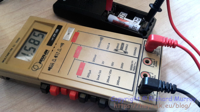
The digital meter is simple to use; selection buttons on the side and a clear legend along with a big bold readout plus a beeper for continuity tests. It is quite nice actually.
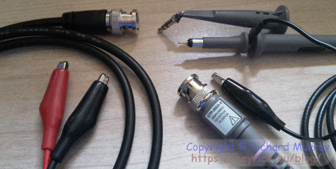
I also picked up some cables.
On the left, a cable supplied with the signal generator. A BNC (bayonet) to croc clips. About a metre long, all but the last 10cm(ish) is shielded.
On the right, finally a proper attenuated probe for the oscilloscope. The probe has a ×1 and ×10 switch on the side (to divide large signals by ten so they don't overload the oscilloscope). There is a detachable ground clip (the black wire to the croc clip), and as can be seen from the photo, I can either have a fine-tipped probe to poke around with, or a cap that fits over the end with a hook to attach to the leg of a component - you can see it in the photo hooked to the end of a dead 3.5mm audio plug. Very nice. I also have a tiny screwdriver (there is a potentiometer in the bayonet lug for tuning the frequency response), as well as three coloured rings to identify the probe. Black, light blue, and the pink that was fitted by default. This discusses tuning test probes, though I only have one adjustment as modern probes have a laser etched (pre-tuned) circuit in the probe head. For €2, it is quite nice to have something so much better than two wires ending in banana plugs!
As an additional bonus, the cable for the signal generator is croc clips to a BNC, so it can be used for the second channel of the oscilloscope.
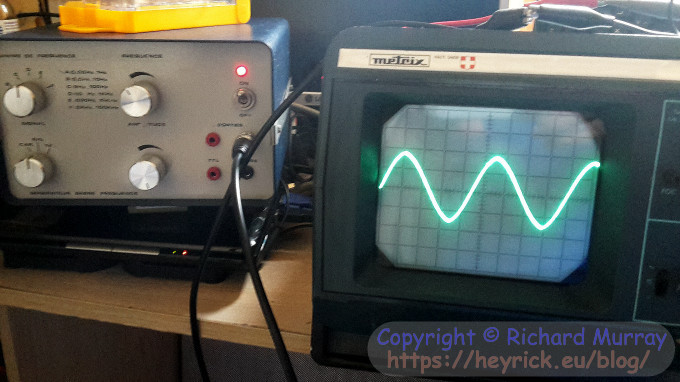
Now for some fun!
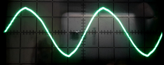
Here's a sine wave at around 50kHz:
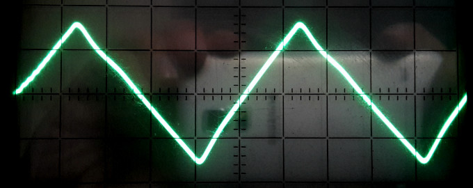
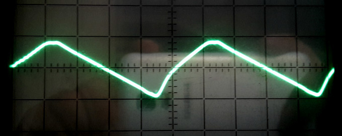
As the frequency increases, the sine starts to attract noise in the switching points (top and bottom of the waveform) and the signal starts to flatten out and more closely resemble the triangle wave, which is this:
The device does triangle wave extremely well. Pick a speed. Any speed (except <cough> 1-4Hz!). A nice solid good looking triangle wave.
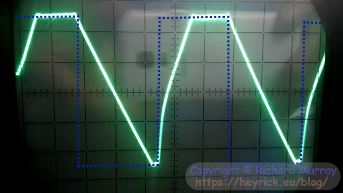
Square wave? That ought to be easy, right? No messing with fancy waveforms, just on and off. Right? Right?
Clock this:
I have drawn in roughly what the square wave ought to look like. The real one, however, is suffering from having a laggy rise time and a long drop-off time. This is more or less the last frequency in which the square wave vaguely resembles a square wave. Your challenge, dear reader, is to tell me at what frequency this is. This will help you:
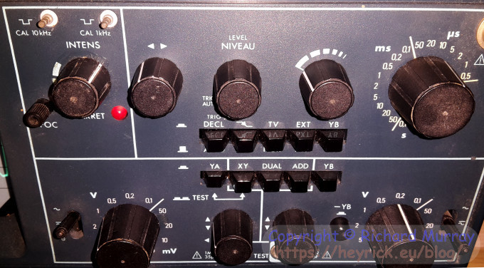
We're using channel A. It is set to 1V/div. The timebase is running at 10µs/div with no adjustment (the knob to the left of the timebase is in the off position). To help, if we are running at 10µs/div, that means a signal taking just one division would be running at 100,000Hz (or 100kHz). Looking at this, the signal is taking about two and a half divisions. So 100kHz ÷ 2.5 means that the best the square wave can manage is a shoddy signal at around 40kHz. Kind of pathetic, but maybe the components inside are "old"? Yeah, that's the excuse we can go with. ☺ Still, I don't forsee needing >40kHz unless I want to upset the bats.
For lulz, here's the square (!) wave at 100kHz:
See? Everything becomes a triangle in the end!
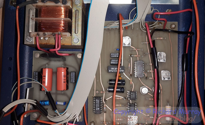
I had, earlier, opened up the signal generator to check that nothing was loose. Here are the simple looking insides:
The device looks to be hand assembled, what with the varying amounts of solder (not wave soldered) and the handwritten captions beside where each wire connects. The big IC in the middle is an Intersil ICL8038 - a precision signal generator. It is this that generates the waveforms, with the other bits of the circuit supplying the timing. Below that, an MCI458 - an inexpensive dual op-amp. Below that, a TL082CP dual JFET op-amp. And to the left? An SN74LS00N quad 2-input positive NAND gate.
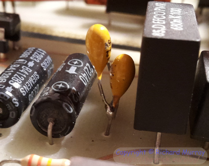
The non-working selector passes into these capacitors. From the right, the capacitors are 6n8, 68n, and 680n. These two are 4k7 and 2k2 which equals 6k9 - what is that? 6.9µF? If so, I would imagine the remaining two on the left are 68µF and 680µF.
There's no shortage of schematics for ICL8038-based signal generators on-line, should I feel the desire to poke around. But, really, 1-4Hz isn't something I envisage requiring...
Your comments:
Please note that while I check this page every so often, I am not able to control what users write; therefore I disclaim all liability for unpleasant and/or infringing and/or defamatory material. Undesired content will be removed as soon as it is noticed. By leaving a comment, you agree not to post material that is illegal or in bad taste, and you should be aware that the time and your IP address are both recorded, should it be necessary to find out who you are. Oh, and don't bother trying to inline HTML. I'm not that stupid! ☺ ADDING COMMENTS DOES NOT WORK IF READING TRANSLATED VERSIONS.
You can now follow comment additions with the comment RSS feed. This is distinct from the b.log RSS feed, so you can subscribe to one or both as you wish.
David Pilling, 16th September 2015, 13:53
8038 marked an era - mid 70's - first integrated signal generator. I built quite a few signal generators just before it came out. Used the resistance of a light bulb technique to stabilise the signal level. Interesting thing about that is that Mr. Hewlett (or Packard) invented the technique back in the 30s.
What to say, if the 'scope was better you'd see how bad the output of the signal generator is...
David Pilling, 16th September 2015, 14:34
...that didn't come out right. My memory is that one can see steps in the 8038 output with a low bandwidth scope. But maybe your signal generator applies some filtering with all those op amps to smooth out the steps. Might explain why things go wrong at high frequencies.
Rick, 16th September 2015, 15:30
The data sheet seems to imply that the sine wave is generated from the triangle wave, which could explain the similarities. The square wave ought to be a simple on/off, so as you say it must surely be the op amps mucking it up. Still, you'd have thought a device claiming to work up to 100kHz might, you know, be capable of it...
David Pilling, 16th September 2015, 16:33
I looked at the datasheet - not what I recalled. I imagined it was pure digital. As you say generates square wave, which is used to make triangle, which makes sine. So primitive they can put the circuit diagram in the datasheet.
The AD9850 is today's equivalent.
Anyway a useful tool, as is the 'scope.
David Pilling, 16th September 2015, 17:27
You could compare the output of the 8038 with what is coming out of the box. People always say capacitors (big electrolytics) don't last, they're the thing to replace in old kit. There's a TTL output on the box, presumably the logic chip is used to generate that.
Rick, 17th September 2015, 14:30
Maybe they could print the schematic in the manual because that was an earlier kinder era when people didn't scream about "intellectual property" and keep everything a secret and pretend that merely discussing how the thing *might* work could incur financial losses greater than the GDP of the country...
This web page is licenced for your personal, private, non-commercial use only. No automated processing by advertising systems is permitted.
RIPA notice: No consent is given for interception of page transmission.