Rick's b.log - entry 2020/04/26 |
| ||||||
mailto: blog -at- heyrick -dot- eu
You are not reading my b.log using HTTPS. You can switch to HTTPS by clicking here. Inside a wireless phone chargerPrinciplesMany years ago, I had a toothbrush that charged itself automatically and magically when it sat in a special cradle.
It wasn't actually magic, it was something known as induction. It is, in fact, the very basis of how transformers work. An alternating current into one set of windings causes magnetic resonance that induces current in another set of windings. By altering the number of windings one each side, it is possible to fairly easily convert 230V or 110V (mains) down to something more useful like 9V or 6V. Since we have a method of transferring power from one set of windings to another using resonance, the logical next step was to do it in a way where the windings on each side could actually be in different units. This is how my toothbrush worked. In the centre of the cradle was a little pole that fit into a matching recess in the bottom of the brush. This was intended that you believe that it was a lug that the toothbrush clipped into, which it was, however it was also a piece of iron in there to act as part of the magnetic arrangement.
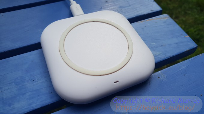 However mobile phones are tiny and flat, as are the little charging pads, such as the one pictured above. There is no magnet or piece of iron between them, indeed it can even work with a small gap between the two, so how does it work? The answer is to shift frequencies. Traditional mains transformers work at either 50Hz or 60Hz (depending on where you are in the world). The typical mobile phone charger starts working at 140kHz using two planar (flat) coils. One in the charger, and another in the phone.
The charger sends out pulses at 140kHz (if it is following the widely used Qi standard) and it monitors these pulses (as it forms a resonant system). When a phone is placed on the charging pad, the resonance changes due to the added coil (in the phone) to the charger can detect its presence.
A look insideInside is this: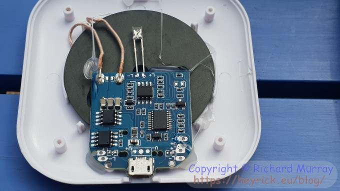 Nothing particularly unusual here, other than the bizarre placement of the LED. There is a coil of fairly thick wire, 10 turns, glued to a piece of iron. This helps inductance and also helps to reduce unwanted emissions. There is a circuit containing four ICs. At a guess, we'll have some sort of controller, a comparator, and two switches. There are no transistors on the board, so I'm guessing one or two of the ICs (likely the two side by side) are taking their function. Given the frequencies and output voltages, probably MOSFETs (basically, a transistor that drives a transistor, to allow it to switch bigger things than a directly controlled transistor would be capable of). As we have resonance at a high frequency, the switching will need to be a pair, a P channel and an N channel (for positive and negative swings). So, let's get a little closer... 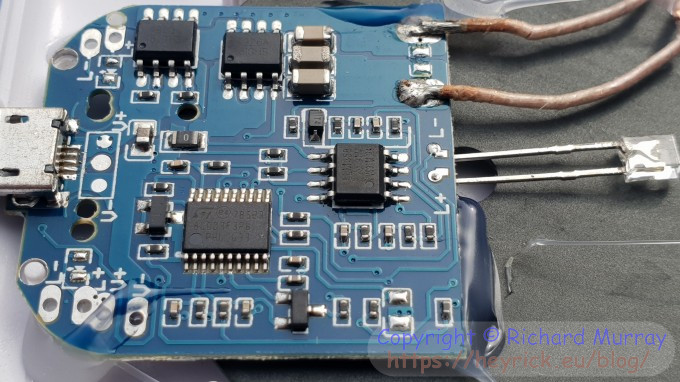 To the right is an LM358, this is a dual operational amplifier. Not a comparator. It is likely that this generates the waveform that the MOSFETs switch? I've not looked at it in too much detail.
Finally, the IC with all the legs. This is an 8S003F3, a microcontroller based around an 8 bit STM8 processor core, 8KiB of Flash, 1KiB of RAM, and 128 bytes of EEPROM. There are the usual selection of GPIO, ADC, timers, etc etc. As the Qi protocol is fairly complex in operation, it is not unexpected to find a microcontroller inside.
In operationHooking my little oscilloscope to the coil, we can see that it sends a signal of +10V to -7V (rounding to nearest whole). The 'scope claims that it is running at 181kHz, but I'm not sure that we can trust that.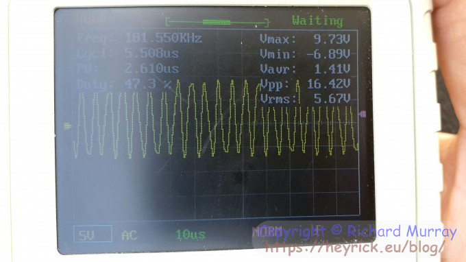 The reason I say we can't trust the frequency is because it is not regular. If we slow the timebase to 50ms, we can see that the pulses actually last for just under 100ms with large gaps in between (notice how the frequency reading is now obviously wrong). 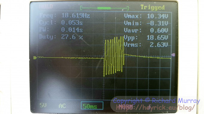 Now if I place my older phone (Samsung S7) in place under the charger (under because everything is upside down due to the clips on the coil), after a moment the waveform changes to a continual ~136kHz with an oscillation of +21V to -9V (or 30V peak to peak). It is interesting that it is unbalanced like this, and not, say, -15V to +15V. 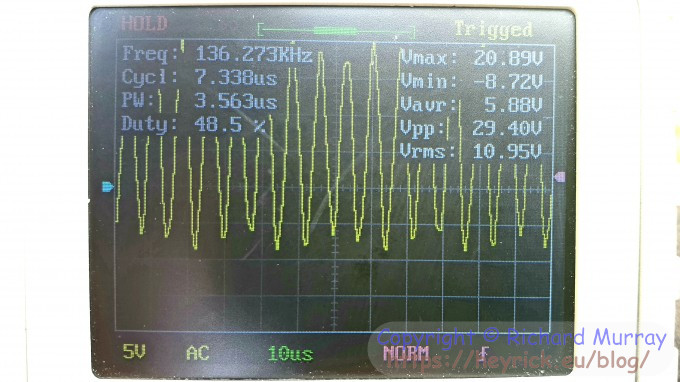 At any rate, something interesting to look at on a sunny Sunday morning! And I didn't get oil all over my hands!
GardeningJust to show that there is more to my life than mowing grass and taking stuff apart, I planted out the sunflowers:  Mom's favourite, the California Poppy (properly named Eschscholzia, which sounds like a reason one would be in hospital), is putting on quite a show:   And with no more outdoor cat, the lizard population has increased. I don't mind the lizards. I just hope the rodent population hasn't increased likewise. I'm not sure I'd trust Wawa to know what to do with a mouse. Certainly, Tiny didn't. The time she met a mouse, they both legged it in opposite directions! 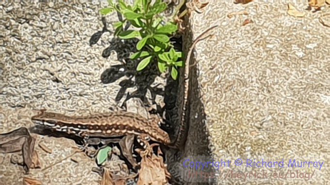
Your comments:Please note that while I check this page every so often, I am not able to control what users write; therefore I disclaim all liability for unpleasant and/or infringing and/or defamatory material. Undesired content will be removed as soon as it is noticed. By leaving a comment, you agree not to post material that is illegal or in bad taste, and you should be aware that the time and your IP address are both recorded, should it be necessary to find out who you are. Oh, and don't bother trying to inline HTML. I'm not that stupid! ☺ ADDING COMMENTS DOES NOT WORK IF READING TRANSLATED VERSIONS.
  
(Felicity? Marte? Find out!)
📺 The SIBA stories 📹
It's a simple substring match.
Last read at 17:51 on 2024/04/20.


| ||||||
| Next entry - 2020/04/28 Return to top of page |
| © 2020 Rick Murray |
| Retrieved from http://www.heyrick.co.uk/blog/index.php?diary=20200426 on 20th April 2024 |