Rick's b.log - entry 2017/01/01 |
| ||||||
mailto: blog -at- heyrick -dot- eu
You are not reading my b.log using HTTPS. You can switch to HTTPS by clicking here. Hello 2017I didn't watch the fireworks in London, nor did I look to see how the extra leap second was dealt with. Instead, I went to bed and listened to Nightwish in the dark. 2016 was a year of death and misery, and I'm wondering what there is worth looking forward to in 2017. Oh yes, this is the year that article 50 is signed, and so begins the slow boring process of watching my citizenship of the EU evaporate. This is the year Trump gets his hands on real power, and no doubt Farage (the good British citizen that he is) will be there in America egging him on. This is the year we can look forward to more death and destruction in the name of imaginary sky fairies. And this is the year France goes to the elections and will probably switch sides to the right. To give you an idea, the current most likely is a Mr. Fillon who appears to consider Thatcher to be a role model. He might want to look long and hard at Thatcher's legacy.I get to go to work tomorrow. Christmas holiday, my week off, has passed in the blink of an eye. Tomorrow is Monday, so back to work. France, so often maligned by Brits for their billions of national holidays, doesn't have the culture of pushing weekend holiday days to the nearest Monday. There's no such thing as "Bank Holiday Monday". Christmas and New Years both fell on Sunday this year, so tant pis, better luck next year!
It's coldOkay, it isn't Canada or Siberia levels of cold, but going from something around +10°C (2-3°C at night) to a day high of less than -2°C is quite a change, and an unwelcome one at that.Still, having ice stick to everything does make for some rather impressive photos. This just says "Brrr!":  Whoa!  The willow tree has turned into the hanging gardens of Babylon:  Whodat?  Here's a video I put together yesterday:
Playing with the oscilloscopeI made a short video of how the oscilloscope behaves with its own 1kHz test video. Of note here is that the oscilloscope is a digital device that takes samples, so there is going to come a point where the device simply ceases to see the 1kHz signal, and the readings will either be a positive voltage (usually) or nothing (less usually) depending on where and how the device performs its sample related to the 1kHz square wave.This isn't unexpected, and is rather akin to those LED torches that have a "longer life" option. What the longer life is doing is saving power by rapidly blinking the LED, instead of having it always on. Your eyes are not sensitive to the flashing, so all you'll normally notice is a slight dimming. If you were to attach the torch (securely!) to a piece of string and swing it around, the blinking may become visible. Well, it's the same with the oscilloscope. At its faster ranges, it can 'see' the blinking, the 1kHz square wave. As you slow the timebase down, it becomes less able to see, until the square wave ceases to be distinguishable as a series of on and off pulses.
The next idea was to have a go at 'seeing' the IR transmissions of my PVR's remote control. The way that the controllers work is basically to send a serial signal that is a start bit followed by a number of data bits. However in order to guard against accidental triggering, such as evening sun or the like being misinterpreted as control signals, the signal is actually modulated by a frequency in the 30-40kHz range. 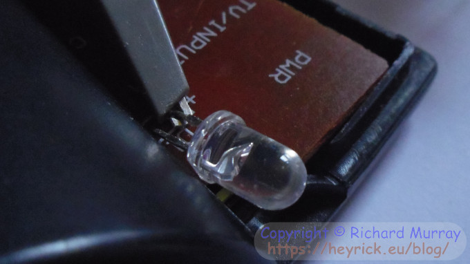 The first step was to select a timebase where each individual pulse sent to the LED is visible. From this, we can determine our carrier frequency. Here is the pulse shown with a 20µS time-per-square. Note the oscilloscope is on the "NORM" setting, so it will capture a data set when it spots a valid trigger, and will hold that on the screen when there is no trigger available. Very useful, that! 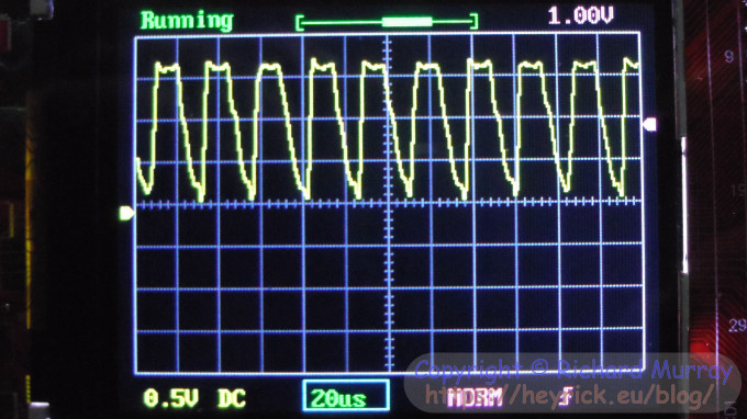
So, we are at the 20µS timebase, which means each square on the screen corresponds to a period of 20 microseconds. To convert this to something more useful, there are a million microseconds per second. Divide that by twenty to give us the value 50000. That means a signal lasting one square will be a 50000Hz (or 50kHz) signal. 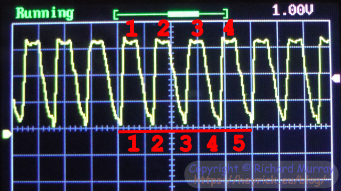 If we pass through five squares to send four pulses, then we can derive the actual frequency as follows. Multiply four (pulses) by fifty (kHz, timebase), then divide that by five (number of 50kHz squares travelled). This gives us the result of forty. In other words, it is a 40kHz signal.
You might wonder - if the oscilloscope has all these clever features and can tell frequencies and such, why don't we just rely upon that? 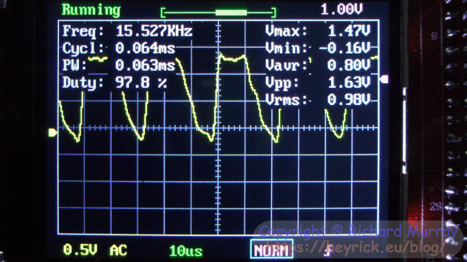 Now we can step out by increasing the timebase until we can see the entire data stream that is sent. This happens when we hit 2ms per square, which corresponds to 500Hz. 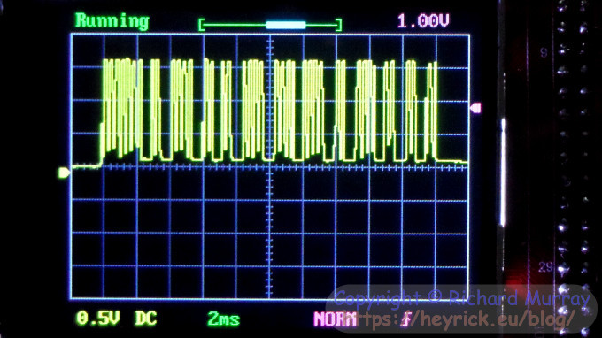 Very very conveniently, the data stream pretty much starts and ends on a square boundary. Covering eleven squares, this gives us a 20ms pulse.
But what are we looking at, actually? Well, there's a big-ass wodge which will be the start bit. This will be used to wake up and synchronise the receiver. This is followed by short bursts and long bursts. 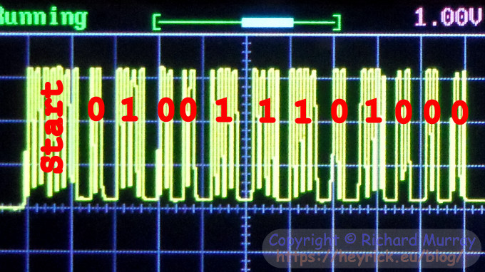
If you look carefully, you will see that the '1' pulses are twice the width of the '0' pulses, and that there appear to be about three "pieces" per square. That is to say, a '0' or a gap is one "piece" long, while a '1' is two "pieces" long. If we divide the square by three, we get 0.66' milliseconds. But this isn't quite right, as all of the pulses are not aligned with the squares. Thus, the start runs for 2.4ms. The '1' bits are 1.2ms long, the '0' bits and inter-bit gaps are 0.6ms long.
The data sent, therefore, is 010011101000. I know my PVR uses standard Sony control codes, so I know it is Sony SIRC; however Googling for "IR 40kHz 0.6ms" gets you going in the right direction. So if we break these apart and flip 'em around, we arrive at a device ID of %00010 and a control code of %1110010. Lookup tables are easy enough to find, so which can be decoded as device ID 2 which is "VTR1", and control code 114 (&72). This does note appear to be listed as anything sensible (in the various places I've looked), in the case of the PVR it is the "Enter" button, but it is quite possible that a VCR has no such functionality and this just happens to be some additional codes that the remote can produce.
Well, there's probably enough there to get started with a transmitter or decoder based upon an Arduino. I don't intend to, I have no need. This was just an exercise in looking at a real life waveform and pulling it to bits. Where this cheap little oscilloscope excelled for me was the one thing my analogue 'scope cannot do - that is respond to a trigger and then keep the waveform visible on-screen even when it isn't there any more. Also, let's face it, the LCD panel - even small as it is at 320×240 and maybe two and a half inches diagonal, is sharper and clearer than an aging cathode ray tube.
Your comments:Please note that while I check this page every so often, I am not able to control what users write; therefore I disclaim all liability for unpleasant and/or infringing and/or defamatory material. Undesired content will be removed as soon as it is noticed. By leaving a comment, you agree not to post material that is illegal or in bad taste, and you should be aware that the time and your IP address are both recorded, should it be necessary to find out who you are. Oh, and don't bother trying to inline HTML. I'm not that stupid! ☺ ADDING COMMENTS DOES NOT WORK IF READING TRANSLATED VERSIONS.
  
(Felicity? Marte? Find out!)
📺 The SIBA stories 📹
It's a simple substring match.
Last read at 10:48 on 2024/04/20.


| ||||||||
| Next entry - 2017/01/06 Return to top of page |
| © 2017 Rick Murray |
| Retrieved from http://www.heyrick.co.uk/blog/index.php?diary=20170101 on 20th April 2024 |